

A grid coupling operating in a mining crusher or steel mill drive transmits thousands of foot-pounds of torque through a flexible spring element that flexes millions of times per week. Without structured maintenance and inspection, the progressive effects of wear, lubrication degradation, and environmental contamination silently reduce coupling capacity until sudden failure halts production. Proactive maintenance transforms the grid coupling from an unpredictable failure risk into a manageable, scheduled component with predictable service intervals.
This guide establishes a practical maintenance and inspection framework for industrial grid coupling installations, covering inspection intervals, condition assessment techniques, lubrication management, and replacement decision criteria that reliability teams can implement immediately.
Establishing a Maintenance Schedule for Grid Coupling Assemblies
Maintenance interval planning begins with classifying the coupling's operating severity. Light-duty applications — centrifugal pumps and fans with uniform loads — typically require inspection every 6-12 months and lubrication every 6 months. Medium-duty applications — conveyors and mixers with moderate shock loading — need inspection every 3-6 months and lubrication every 3-4 months. Heavy-duty applications — crushers, grinding mills, and reversing drives — demand inspection every 2-3 months and lubrication every 2-3 months.
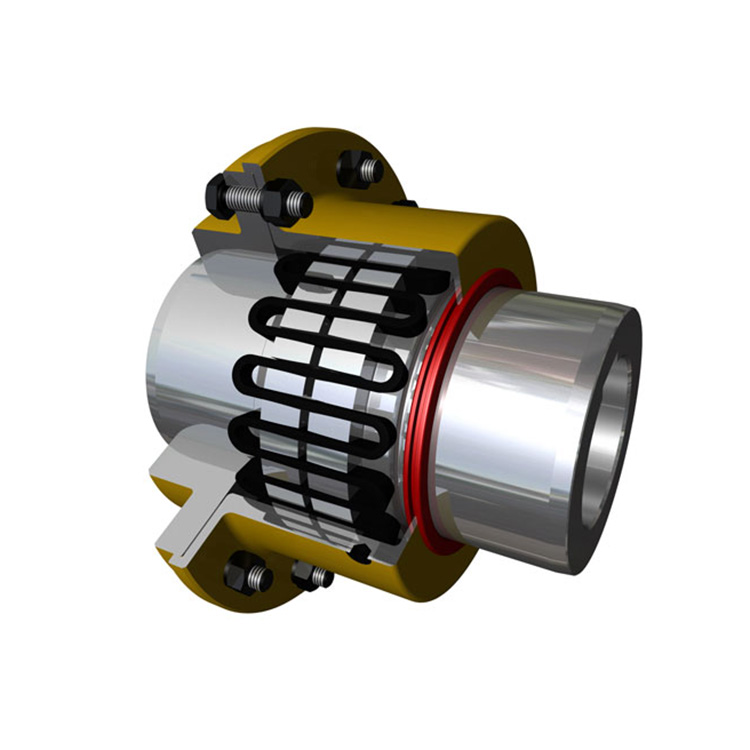
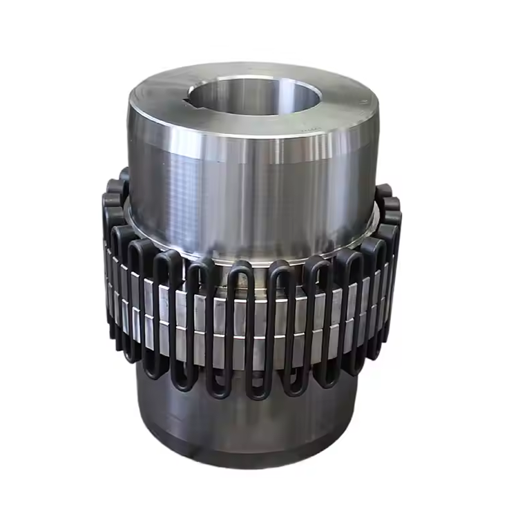
These baseline intervals should be adjusted based on field experience with the specific installation. Applications that consistently show minimal wear during inspections can extend intervals progressively, while those showing accelerated wear require shortened intervals. The goal is to establish condition-based intervals that reflect actual operating conditions rather than generic time-based schedules that may over-maintain benign applications and under-maintain severe ones.
Seasonal considerations affect maintenance timing for outdoor installations. Couplings exposed to temperature extremes, monsoon rainfall, or winter freeze-thaw cycles experience accelerated seal and lubrication degradation. Schedule pre-season and post-season inspections for outdoor equipment to catch and correct environmental damage before it progresses to coupling failure.
Visual Inspection Procedures and Checkpoints
External visual inspection of a grid coupling provides the first indication of developing problems. Begin with the cover condition — check for cracks, dents, and corrosion that compromise the sealed environment protecting the grid and hub teeth. Cover damage allows lubricant leakage and contaminant ingress, both of which accelerate internal component degradation. Document any cover damage with photographs for comparison during future inspections.
Seal condition assessment focuses on visible grease accumulation around the seal lips, which indicates seal failure allowing lubricant to escape. Conversely, rust or discoloration at the seal interface suggests that contaminants are entering the coupling housing. Both conditions require seal replacement at the next available maintenance window — delaying seal service transforms a minor repair into a major coupling overhaul when the grid and hub teeth sustain damage from the compromised sealing environment.
Check bolt tightness on the cover halves using a calibrated torque wrench set to the manufacturer's specified value. Cover bolt loosening from vibration is a common finding during routine inspections. Loosened bolts allow cover separation that breaks the seal, and the resulting grease loss and contamination lead to rapid grid and tooth wear if not corrected promptly.
Inspect the surrounding area for grease splatter patterns that indicate the direction and volume of any leakage. Small amounts of grease weeping from the seal during initial operation after lubrication are normal. Active grease leakage that continues between lubrication intervals indicates a seal or cover problem requiring correction.
Internal Inspection and Grid Condition Assessment
Internal inspection requires disassembling the grid coupling cover and removing the grid element. This level of inspection is typically performed during scheduled outages or when external inspection findings suggest internal problems. The grid element is the primary wear component and provides the most valuable condition information for maintenance planning.
Grid cross-section measurement using digital calipers at multiple positions along the grid length quantifies material loss from wear and corrosion. Compare measured dimensions to the grid's original cross-section specification — grids showing cross-section reduction exceeding 15% should be replaced regardless of operating hours. Grids with reduction between 10-15% require more frequent monitoring but may continue in service if corrosion is not the primary degradation mechanism.
Visual examination of grid surfaces reveals crack initiation sites, corrosion pitting, and surface fatigue patterns. Cracks at the grid segment transitions — the points where individual loops of the serpentine grid change direction — indicate fatigue from cyclic loading. Surface pitting from corrosion reduces effective cross-section and creates stress concentrations that accelerate fatigue crack propagation. Any grid showing visible cracks requires immediate replacement.
Hub tooth surface condition provides complementary information about operating conditions. Uniform tooth wear across all teeth suggests normal lubricated service, while localized wear on specific teeth indicates misalignment concentrating load on a few tooth pairs. Tooth surface pitting indicates lubrication breakdown or contamination. Tooth surface scoring — deep linear scratches along the tooth face — suggests abrasive contamination in the lubricant that must be resolved before grid replacement, or the new grid will experience the same accelerated wear.
Lubrication Management Best Practices
Lubrication quality is the single most influential maintenance factor for grid coupling service life. The lubricant performs three critical functions: reducing friction between the grid and hub teeth during flexing, dissipating heat generated by this friction, and protecting exposed metal surfaces from corrosion. Degradation in any of these functions directly accelerates grid and tooth wear.
Grease sampling during routine lubrication services provides the earliest indication of developing problems. Fresh coupling grease is typically a uniform, smooth consistency with a characteristic color determined by the additive package. Discolored or darkened grease indicates thermal degradation or contamination. Gritty texture suggests metallic wear particles from grid or tooth wear. Separated grease — where the base oil has separated from the thickener — indicates mechanical breakdown from excessive shear or thermal cycling.
Grease compatibility is a frequently overlooked maintenance consideration. When replenishing or replacing coupling grease, the new grease must be compatible with the residual old grease remaining in the coupling. Incompatible greases can react chemically, causing softening, hardening, or separation that destroys lubricating properties. If changing grease types, remove all old grease from the coupling housing before installing the new product.
Lubricant storage conditions affect performance. Grease stored in hot environments or in direct sunlight degrades faster than properly stored product. Use FIFO (first-in, first-out) inventory rotation and store grease containers sealed in a cool, dry location. Opened containers should be resealed immediately after use to prevent contamination and moisture absorption.
Vibration Analysis for Condition Monitoring
Vibration analysis provides the most effective non-intrusive method for monitoring grid coupling condition during operation. Healthy grid couplings produce low vibration levels at the coupling position — typically below 0.1 inches per second velocity for most industrial speeds. Increases in vibration amplitude at specific frequencies indicate developing problems that warrant investigation.
Vibration at 1X running frequency suggests imbalance or misalignment — conditions that may originate from the coupling or from the connected equipment. Vibration at 2X running frequency indicates angular misalignment specifically, while vibration at multiple higher harmonics suggests mechanical looseness in the coupling assembly or its mounting hardware.
Changes in vibration signature over time provide more diagnostic value than absolute amplitude readings. Establish baseline vibration data for each coupling immediately after installation, then compare periodic readings to these baselines. A gradual increasing trend indicates progressive wear or alignment degradation, while a sudden step change suggests a discrete event — such as a shock load or foreign object impact — that may have damaged the grid or hub teeth.
Permanently installed vibration monitoring systems on critical grid coupling installations provide continuous condition data without requiring technician visits for each reading. These systems enable alarm thresholds that alert maintenance teams to developing problems, shifting maintenance from calendar-based scheduling to true condition-based intervention.
Replacement Decision Criteria and Planning
Determining when to replace a grid coupling grid element involves balancing remaining useful life against the cost and risk of failure. The primary replacement triggers include: cross-section reduction exceeding 15% of original dimensions, visible cracking or severe corrosion on the grid, tooth surface deterioration on the hubs, and vibration trend data showing progressive degradation approaching alarm thresholds.
Proactive grid replacement during planned outages costs a fraction of emergency replacement during unplanned shutdowns. A planned grid replacement during a scheduled maintenance window typically requires 2-4 hours, while an emergency replacement during production may take 8-24 hours when equipment cooling, access, and component procurement time are included. The production loss from unplanned downtime often exceeds the annual coupling maintenance budget by orders of magnitude.
Complete coupling replacement — including hubs — becomes necessary when hub tooth profiles show significant wear, pitting, or corrosion that prevents proper grid engagement. Hub replacement intervals are typically 3-5 times longer than grid replacement intervals in well-maintained installations, making hub replacement a less frequent but more consequential maintenance event that should be planned well in advance.
Spare parts inventory strategy should reflect the criticality and lead time of each coupling component. Grid springs — the most frequently replaced component — should be stocked on-site for critical installations. Hub assemblies with custom bore specifications may have manufacturing lead times of 4-8 weeks, making advance procurement essential for planned replacements and emergency preparedness.
Frequently Asked Questions
How often should I inspect my grid coupling?
Inspection frequency depends on operating severity. Heavy-duty applications — crushers, mills, reversing drives — require internal inspection every 2-3 months. Medium-duty applications need inspection every 3-6 months. Light-duty applications can extend to 6-12 months. Adjust intervals based on actual condition findings — if inspections consistently show minimal wear, extend intervals progressively. If wear is more severe than expected, shorten intervals accordingly.
When should I replace the grid element versus the entire coupling?
Replace the grid element when cross-section reduction exceeds 15% of original dimensions, when visible cracks or severe corrosion are present, or when vibration trend data indicates progressive deterioration. Replace the entire coupling — including hubs — when hub tooth surfaces show significant pitting, scoring, or wear that compromises proper grid engagement. Hub replacement is required far less frequently than grid replacement in well-maintained installations.
Can vibration analysis predict grid coupling failure?
Vibration analysis detects developing coupling problems weeks to months before failure, enabling planned maintenance interventions. However, it cannot precisely predict failure timing because the relationship between vibration amplitude and remaining life depends on multiple variables including load severity, lubrication condition, and material properties. Use vibration data to schedule inspections and replacement planning, not as a precise countdown timer to failure.
What grease should I use for my grid coupling?
Use the coupling manufacturer's specified grease — this is not an area for substitution. Grid coupling greases are formulated with specific EP additives, base oil viscosities, and thickener systems matched to the coupling's operating conditions. If the manufacturer's product is unavailable, consult their technical support for approved alternatives. Never mix incompatible greases, as chemical reactions between formulations can destroy lubricating properties.
Conclusion
Structured maintenance and inspection programs transform the industrial grid coupling from an unpredictable failure risk into a managed reliability asset. Visual inspection, internal condition assessment, lubrication management, vibration monitoring, and informed replacement decision-making together form a comprehensive maintenance framework that maximizes coupling service life while minimizing unplanned downtime. Facilities that implement these practices consistently achieve grid coupling service life 2-3 times longer than those relying on reactive maintenance, with corresponding reductions in total ownership cost and production loss. The coupling maintenance investment pays for itself many times over in avoided emergency shutdowns and extended equipment reliability.
References
AGMA 9002-B04 — Flexible Couplings: Design Considerations and Selection
ISO 14691:2008 — Flexible Couplings: Design, Selection and Application
Soh, Y. et al. (2018). "Wear Mechanisms in Metallic Flexible Couplings Under Cyclic Loading." Wear, 398-399, 46-58.
API 671 — Special Purpose Couplings for Petroleum, Chemical, and Gas Industry Services
ISO 17359:2018 — Condition Monitoring and Diagnostics of Machines: General Guidelines