

A properly installed grid coupling delivers years of reliable service in mining crushers, steel mill drives, and heavy material handling equipment. An improperly installed one fails within months — sometimes weeks. The difference between these outcomes is not the coupling itself but the quality of the installation process. Field service records consistently show that installation errors account for 60-70% of premature grid coupling failures, making proper installation technique the single most impactful factor in coupling reliability.
This article provides field-tested installation best practices for grid coupling assemblies, covering preparation, alignment, hub mounting, grid installation, lubrication, and post-installation verification. These practices draw from decades of field experience across heavy industrial applications and reflect the procedures that experienced maintenance teams follow to achieve maximum coupling service life.
Pre-Installation Preparation and Inspection
Before beginning installation, verify that all components match the bill of materials and that no damage occurred during shipping. Check hub bore dimensions against shaft dimensions using calibrated instruments — do not rely on the catalog specifications alone, as manufacturing variations may produce parts at the extreme ends of tolerance ranges. Verify that the grid element matches the coupling size — installing a grid sized for a different coupling model creates immediate operational problems.
Inspect shaft surfaces for burrs, nicks, and corrosion that would interfere with hub seating. Use a fine stone or emery cloth to remove minor surface imperfections, then clean the shaft thoroughly with solvent to remove oil, grease, and debris. The shaft must present a clean, smooth surface for the hub to seat properly against the shaft shoulder without gaps or tilt.
Verify that the coupling cover and seals are undamaged. Cover dents can restrict grid movement, while damaged seals allow lubricant leakage and contaminant ingress. Replace any suspect components before proceeding — it is far less expensive to replace a damaged seal during installation than to shut down equipment for seal replacement after only weeks of operation.
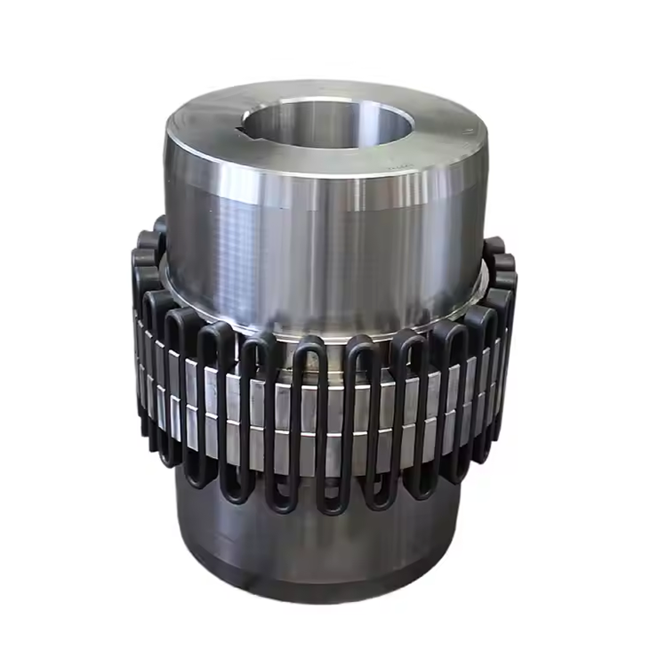
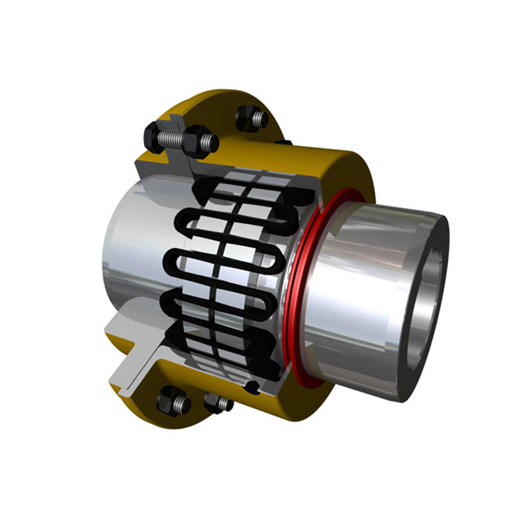
Hub Mounting and Shaft Alignment Procedure
Install both coupling hubs on their respective shafts before performing alignment measurements. This sequence captures hub-related runout in the alignment data, ensuring that the measured misalignment reflects actual coupling operating conditions rather than theoretical shaft centerline positions alone.
For clearance-fit hubs, slide the hub onto the shaft until it seats firmly against the shaft shoulder. Verify seating by attempting to insert a 0.001-inch feeler gauge between the hub face and the shaft shoulder — no gap should be detectable. Install the key per DIN 6885 or ANSI B17.1 specifications, ensuring proper side fit that prevents key rocking under torsional loading.
For interference-fit hubs, heat the hub using controlled methods — oil bath or induction heater — to the temperature calculated from the interference value and bore diameter. Never use an open flame for hub heating, as uneven heating creates thermal distortion and potentially alters the material's metallurgical structure. Install the hub quickly before it cools, positioning it firmly against the shaft shoulder with axial pressure until it seats completely.
Perform precision shaft alignment using dual-laser alignment instruments. Target alignment values at no more than 50% of the coupling's rated misalignment capacity in both angular and parallel directions. Document the as-left alignment readings for baseline reference during future alignment verification checks.
Grid Element Installation: The Critical Step
Grid element installation requires care to avoid damaging the serpentine spring during assembly. The grid must be wound — progressively flexed and inserted — into the hub tooth profile, engaging each tooth pair sequentially around the coupling circumference. Forcing the grid into position without proper winding technique bends individual grid segments beyond their elastic limit, creating permanent deformation that reduces both torque capacity and fatigue life.
Most grid coupling manufacturers provide specific installation tools and procedures for their grid designs. Use these tools rather than improvised alternatives. Installation levers designed for the specific coupling size apply force at the correct angle and location to flex the grid into the hub profile without overstressing individual segments. Improvised tools — screwdrivers, pry bars, or hammers — frequently damage grid surfaces and create stress concentrations that initiate premature fatigue failures.
After installation, verify that the grid seats fully within the hub tooth profile at all positions. Run your finger along the grid surface — it should sit flush with or slightly below the hub tooth tips with no segments protruding above the tooth profile. Protruding segments indicate incomplete seating that will produce vibration during operation and accelerated wear at the raised contact points.
Check grid end clearance — the axial space between the grid ends and the cover — to ensure the grid can flex freely without end-to-end binding. Grid end gaps vary by coupling size but typically range from 0.030 to 0.125 inches per side. Insufficient end clearance prevents the grid from flexing through its full design amplitude, reducing misalignment accommodation and concentrating flexing stress in a smaller portion of the grid length.
Lubrication: Getting the Fill Right
Proper lubrication of the grid coupling is essential for grid fatigue life and tooth surface protection. The lubricant forms a film between the grid and hub teeth during flexing, reducing friction, dissipating heat, and protecting metal surfaces from corrosion. Without adequate lubrication, metal-to-metal contact at the grid-tooth interface produces rapid wear, elevated operating temperatures, and dramatically reduced grid life.
Fill the coupling housing with the manufacturer's recommended grease to the specified level. Overfilling is as problematic as underfilling — excess grease pressurizes the housing, forcing grease past the seals and creating a mess on surrounding equipment. Excess grease also generates churning heat at high speeds that accelerates grease degradation. The correct fill level typically leaves 25-50% of the housing volume as void space for grease displacement during operation.
Use only the specified grease type. Grid coupling greases are formulated with extreme pressure additives, specific base oil viscosities, and mechanical stability characteristics matched to the operating conditions of the coupling. Substituting a general-purpose grease may appear to work initially but often fails to maintain adequate film strength under the combined effects of load, temperature, and flexing that characterize grid coupling operation.
For horizontal installations, the fill plug location determines the grease level. Most coupling covers include a grease fitting and a level plug — fill through the fitting until grease flows from the level plug opening, then replace both plugs. For vertical installations, follow the manufacturer's specific fill procedure, which typically specifies a measured grease quantity rather than a fill-to-level approach.
Cover Assembly and Seal Installation
After grid installation and lubrication, assemble the coupling cover halves around the hub assembly. Cover bolt torque specifications must be followed precisely — undertorqued bolts allow cover separation and grease leakage, while overtightened bolts distort the cover and crush the seal, creating leakage paths that allow both grease egress and contaminant ingress.
Seal installation requires attention to orientation and condition. Labyrinth seals — common in industrial grid coupling designs — rely on precise axial positioning to maintain the labyrinth gap that excludes contaminants while retaining grease. Damaged, twisted, or improperly seated seals fail to perform this function, exposing the grid and hub teeth to environmental contamination that accelerates wear and corrosion.
On couplings equipped with grease fittings and level plugs, verify that both are properly installed and sealed. The grease fitting must be clean and free of debris before attaching the grease gun — contaminated grease injected into the coupling introduces abrasive particles directly to the grid-tooth contact surfaces. Apply a small amount of clean grease to the fitting before each lubrication service to flush any contaminants from the fitting orifice.
Post-Installation Verification and Commissioning
After completing the grid coupling installation, perform a comprehensive verification before returning the equipment to service. Rotate both shafts manually through at least one full revolution, feeling for any binding, rubbing, or uneven resistance. A properly installed grid coupling should rotate smoothly with only the slight resistance of the grid flexing within the hub tooth profile.
Run the equipment at low speed initially, monitoring vibration levels at the coupling position using portable vibration instruments. Compare startup vibration readings to baseline data from previous installations of the same coupling type and size. Elevated vibration at 1X running frequency suggests residual misalignment or hub runout, while vibration at higher harmonics may indicate grid seating issues or cover interference.
After 24-48 hours of operation, check coupling operating temperature using infrared thermometry or contact temperature measurement. Normal operating temperature should not exceed ambient by more than 40-50°F for properly installed and lubricated grid couplings. Higher temperature differentials indicate potential problems — inadequate lubrication, excessive misalignment, or overload conditions — requiring investigation before they progress to failure.
Recheck alignment after the first thermal cycle. Equipment alignment changes between cold and hot operating conditions, and the initial alignment verification should be repeated with the equipment at normal operating temperature. Adjust alignment if hot readings exceed 75% of the coupling's rated misalignment capacity.
Frequently Asked Questions
What is the most common installation mistake with grid coupling assemblies?
Forcing the grid into the hub without proper winding technique ranks as the most frequent and damaging installation error. This practice bends grid segments beyond their elastic limit, creating permanent deformation that reduces torque capacity and fatigue life. Always use the manufacturer's installation tool and follow the specified winding procedure for the coupling size.
How much misalignment is acceptable after installation?
Target actual operating misalignment at no more than 50% of the coupling's rated misalignment capacity in both angular and parallel directions. This margin accommodates the dynamic misalignment changes that occur during thermal cycling and load variation. Operating continuously at rated misalignment capacity dramatically reduces grid service life and increases the probability of premature failure.
Can I reuse a grid element after disassembly?
Grid elements can be reused if inspection confirms that cross-section dimensions remain within 85% of original values and no visible cracking, corrosion, or permanent deformation is present. However, many reliability-focused facilities replace grids as a matter of policy during any coupling disassembly, treating the grid as a consumable component with predictable replacement cost versus the uncertain reliability of a reused element.
How tight should the cover bolts be on a grid coupling?
Follow the coupling manufacturer's published torque specifications for cover bolts. Typical values range from 15 to 60 foot-pounds depending on bolt size and coupling model. Use a calibrated torque wrench — do not estimate bolt tightness by feel. Both undertightening (allowing cover separation) and overtightening (distorting the cover and crushing seals) create problems that reduce coupling reliability and service life.
What should I check after the first week of operation?
Verify coupling operating temperature, recheck alignment with equipment at normal operating temperature, and inspect for any visible grease leakage from the cover seals. Compare vibration readings to baseline measurements taken during commissioning. Any significant changes in these parameters within the first week indicate installation issues requiring prompt investigation before they cause equipment damage.
Conclusion
Proper grid coupling installation is a systematic process where each step — preparation, hub mounting, alignment, grid installation, lubrication, cover assembly, and post-installation verification — contributes to the coupling's long-term reliability. Field experience consistently demonstrates that installations following these best practices achieve grid service life 2-3 times longer than those where shortcuts are taken. The additional time invested in proper installation technique pays for itself many times over through reduced maintenance frequency, fewer unplanned shutdowns, and lower total cost of ownership across the coupling's operating life.
References
AGMA 9002-B04 — Flexible Couplings: Design Considerations and Selection
ISO 14691:2008 — Flexible Couplings: Design, Selection and Application
API 671 — Special Purpose Couplings for Petroleum, Chemical, and Gas Industry Services
Mancuso, J.R. (1999). Couplings and Joints: Design, Selection, and Application, 2nd Edition. Marcel Dekker.
Brasel, J.N. (2010). "Failure Analysis of Grid Couplings in Heavy-Duty Applications." Journal of Mechanical Design, 132(8), 081001.