

In heavy industrial power transmission, the drum gear coupling serves as a critical interface between driving motors and driven equipment — from steel mill stands and mine hoists to marine propulsion drives and petrochemical compressors. Its combination of high torque density, all-metal construction, and moderate misalignment accommodation makes it the preferred coupling type for applications where elastomeric couplings lack the torque capacity and gear couplings with straight teeth lack the misalignment performance needed for reliable operation.
This article examines the role of the drum gear coupling within industrial power transmission systems, analyzing how its design characteristics translate into application-specific performance advantages and specification considerations for engineers and procurement professionals.
The Role of Drum Gear Coupling in Drivetrain Architecture
A power transmission drivetrain consists of a power source, a coupling system, and driven equipment. The drum gear coupling occupies the coupling position, transmitting torque while accommodating the shaft-to-shaft misalignment that inevitably exists in real installations. Its position in the drivetrain makes it responsible for protecting both the driving motor and the driven equipment from the harmful effects of misalignment, torsional vibration, and thermal expansion.
Unlike rigid couplings that force connected shafts into alignment, the drum gear coupling allows controlled angular and parallel displacement through the rocking motion of its crowned teeth within the internal sleeve tooth spaces. This flexibility absorbs the residual misalignment that remains after precision laser alignment — typically 0.002 to 0.010 inches of offset and 0.05° to 0.15° of angularity — while transmitting full rated torque without slippage or energy loss.
In system-level design, the coupling's torsional stiffness influences the drivetrain's natural frequencies and dynamic response. Drum gear couplings are relatively stiff in torsion compared to elastomeric designs, transmitting torsional vibration with minimal attenuation. This characteristic requires torsional analysis during the design phase to ensure that no system natural frequency coincides with an excitation frequency from the driver or driven equipment.
Torque Transmission Performance Under Variable Loads
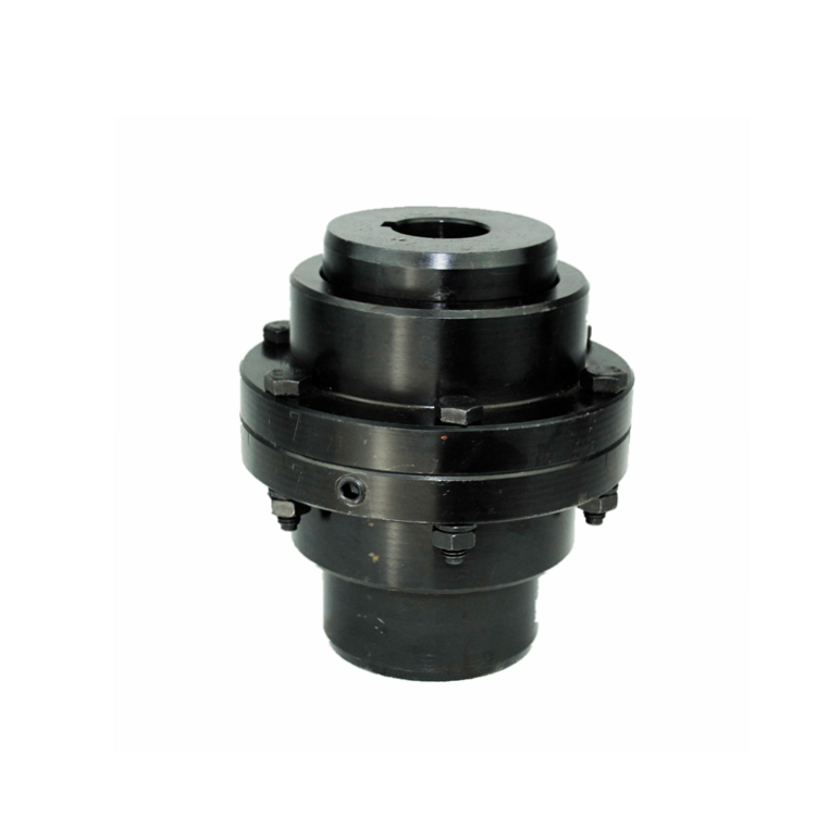
The drum gear coupling transmits torque through multiple tooth pairs engaged simultaneously between the external hub teeth and internal sleeve teeth. This distributed load sharing provides inherent overload capacity — when peak torque exceeds nominal loading, additional tooth contact area engages progressively, distributing the load across more teeth rather than concentrating it on a few. This progressive engagement provides transient overload capacity of 200-300% of rated torque for short-duration events without permanent deformation.
Continuous operation under variable loading conditions requires careful coupling sizing using appropriate service factors. Applications with uniform loads — centrifugal pumps and fans — operate at service factors of 1.0-1.3. Moderate shock loading from reciprocating compressors or conveyors requires factors of 1.5-2.0. Heavy shock applications — crushers, hammer mills, and reversing drives — demand service factors of 2.0-3.0 to prevent tooth surface fatigue under repeated peak loading.
Directional loading affects tooth wear patterns and service life. Unidirectional applications develop tooth wear concentrated on the driving flank, while bidirectional (reversing) applications distribute wear across both flanks. Reversing service typically reduces coupling life by 30-40% compared to unidirectional operation at equivalent torque levels, a factor that must be reflected in maintenance scheduling for reversing applications.
Misalignment Accommodation in Real-World Installations
Misalignment between driver and driven shafts arises from multiple sources in industrial installations. Initial installation tolerance, thermal growth during operation, foundation settlement over time, and pipe strain from connected process systems all contribute to the total misalignment that the drum gear coupling must accommodate. Understanding these sources and their combined effect is essential for proper coupling specification.
Thermal growth represents the largest single contributor to operating misalignment in many process plant applications. A motor operating at full load may experience frame temperature rises of 40-60°F above ambient, expanding the motor frame vertically by 0.006-0.010 inches per foot of centerline height. This growth changes shaft alignment between cold installation conditions and hot operating conditions, requiring the coupling to accommodate the resulting angular and offset changes without exceeding rated misalignment limits.
The drum-shaped tooth profile provides superior misalignment accommodation compared to straight-tooth gear couplings. Crown modification distributes tooth contact across the tooth face even under angular misalignment, preventing the edge loading that occurs with straight teeth. This contact distribution reduces peak tooth contact stress by 25-40% compared to straight-tooth designs under equivalent misalignment, directly translating to longer tooth life and more predictable service intervals.
Operating beyond rated misalignment accelerates tooth surface wear through increased sliding velocity at the tooth interface. Each degree of angular misalignment above rated capacity increases tooth sliding distance per revolution, generating additional friction heat and accelerating tooth surface degradation. Maintaining actual misalignment at 50-60% of rated capacity provides adequate margin for dynamic misalignment variations while maximizing coupling service life.
Speed Considerations for Drum Gear Coupling Applications
Operating speed affects drum gear coupling performance through centrifugal force, lubrication dynamics, and balance requirements. At moderate speeds below 3,600 RPM, standard coupling designs perform reliably with normal lubrication and balance specifications. Higher-speed applications require enhanced specifications that address speed-related effects on coupling components.
Centrifugal force acting on the sleeve increases with the square of rotational speed. At very high speeds, centrifugal expansion of the sleeve reduces the interference between sleeve and hub teeth, potentially allowing sleeve movement relative to the hubs. High-speed coupling designs incorporate sleeve retention features — including snap rings, bolts, or shrink-fit construction — that prevent sleeve displacement under centrifugal loading.
Lubrication at high speeds faces churning losses as the coupling rotates through the grease fill. Excessive grease generates fluid friction that produces heat and increases power consumption. High-speed drum gear coupling designs typically specify reduced grease fill quantities and lower-viscosity lubricants to minimize churning effects while maintaining adequate tooth surface lubrication.
Balance quality requirements become increasingly stringent at higher speeds. Standard industrial couplings are balanced to grade G6.3 per ISO 21940, suitable for speeds up to approximately 3,600 RPM. Higher-speed applications require G2.5 or G1.0 balance grades achieved through precision machining, material removal, or addition of balance correction weights. Inadequate balance produces vibration forces that damage bearings and reduce equipment reliability.
Application-Specific Design Considerations
Steel rolling mill drives place extreme demands on drum gear coupling performance. Intermittent biting loads during slab reduction generate peak torque spikes reaching 2-3 times nominal motor torque, combined with rapid acceleration and deceleration during pass sequences. Couplings in these applications require high service factors, hardened tooth surfaces, and robust lubrication systems that maintain oil film integrity under the combined effects of shock loading and thermal cycling from hot steel radiation.
Marine propulsion applications demand couplings that accommodate hull flexing and differential thermal expansion between the engine — operating at temperatures exceeding 200°F — and the gearbox, which may be significantly cooler. The coupling must also handle torsional vibration from the diesel engine's firing impulses without transmitting destructive resonance to the gear train. Marine-specified drum gear couplings incorporate enhanced sealing, corrosion-resistant materials, and balance grades appropriate for the continuous duty requirements of ocean-going service.
Mining applications expose couplings to dust, moisture, and shock loading from ore crushing and conveyor jam events. Sealed coupling designs with grease lubrication protect internal tooth surfaces from abrasive contamination while providing reliable torque transmission under heavy loads. Mining-grade couplings typically specify oversized service factors and hardened tooth surfaces that resist wear from the combination of shock loading and moderate misalignment common in underground and open-pit installations.
Lubrication System Design for Reliable Operation
Lubrication quality directly determines the service life of a drum gear coupling in any application. The sliding contact between external hub teeth and internal sleeve teeth generates friction that must be controlled by a lubricant film separating the contacting surfaces. Without adequate lubrication, metal-to-metal contact produces adhesive wear, surface scoring, and rapid tooth profile degradation that leads to coupling failure.
Grease lubrication is the standard method for enclosed drum gear couplings. Semi-fluid grease with extreme pressure (EP) additives fills the coupling housing, coating tooth surfaces and providing the film necessary to prevent metal-to-metal contact under load. NLGI Grade 0 or 1 consistency provides the flow characteristics needed for the grease to redistribute within the coupling during rotation, ensuring that all tooth surfaces receive adequate lubrication.
Lubrication interval planning should consider operating speed, load severity, and environmental contamination potential. Standard recommendations call for grease replenishment every 6-12 months for normal-duty applications, with intervals shortened to 3-6 months for heavy-duty or contaminated environments. During each lubrication service, inspect the discharged grease for metallic particles that indicate internal wear requiring further investigation.
Frequently Asked Questions
What torque range can a drum gear coupling handle?
Drum gear couplings span a wide torque range depending on size and model. Standard industrial sizes handle continuous torque from approximately 100 Nm to over 500,000 Nm. Special mining and steel mill configurations extend this range further. The appropriate size for a specific application is determined by applying the correct service factor to nominal operating torque and selecting a coupling with rated capacity equal to or exceeding the adjusted torque requirement.
How does a drum gear coupling differ from a disc coupling?
Drum gear couplings use metal gear tooth mesh for torque transmission and accommodate misalignment through tooth rocking, requiring lubrication. Disc couplings use flexible metallic discs that flex to accommodate misalignment without internal sliding contact, requiring no lubrication. Gear couplings offer higher torque density and better shock load capacity; disc couplings offer lower maintenance and cleaner operation in environments where grease leakage is unacceptable.
Can a drum gear coupling be used in vertical applications?
Yes, with appropriate design modifications. Vertical installations require thrust-bearing capability to support the weight of the coupling and any attached components hanging on the lower shaft. Special sealing arrangements prevent grease from draining downward away from the tooth mesh. Most coupling manufacturers offer vertical-mount versions with modified covers, seal configurations, and thrust washers designed specifically for vertical shaft applications.
What causes premature tooth wear in drum gear couplings?
The most common causes include inadequate or incorrect lubrication, operation beyond rated misalignment, overload conditions exceeding the coupling's service factor, and contamination of the lubricant by water or abrasive particles. Each cause produces characteristic wear patterns that experienced inspectors can identify during disassembly: uniform wear suggests lubrication deficiency, localized wear indicates misalignment, and pitting or scoring suggests contamination or overload.
How does thermal growth affect coupling alignment?
Thermal growth causes equipment frames to expand as operating temperatures increase, shifting shaft positions relative to cold alignment conditions. A typical motor may grow 0.008-0.012 inches vertically from cold to hot operating conditions. This growth must be accounted for during initial alignment by deliberately misaligning the shafts in the cold condition so that they achieve proper alignment at operating temperature. Failure to compensate for thermal growth results in the coupling operating near or beyond its rated misalignment under hot conditions.
Conclusion
The drum gear coupling provides a proven, high-performance solution for industrial power transmission systems demanding high torque capacity, moderate misalignment accommodation, and reliable operation across wide temperature ranges. Understanding its performance characteristics — torque transmission behavior under variable loads, misalignment accommodation limits, speed effects, and lubrication requirements — enables engineers to specify and maintain drum gear couplings that deliver maximum service life and equipment protection across the demanding applications where this coupling technology excels.
References
AGMA 9002-B04 — Flexible Couplings: Design Considerations and Selection
ISO 14691:2008 — Flexible Couplings: Design, Selection and Application
API 671 — Special Purpose Couplings for Petroleum, Chemical, and Gas Industry Services
Mancuso, J.R. (1999). Couplings and Joints: Design, Selection, and Application, 2nd Edition. Marcel Dekker.
ISO 21940-11:2016 — Mechanical Vibration: Rotor Balancing