

A grid coupling fails in a small number of predictable ways, and most of them announce themselves weeks or months before the breakdown. The grid element wears progressively. The seal leaks before the grease is gone. The lubrication breaks down before the tooth surfaces weld. The misalignment wear shows in vibration trending before the coupling is damaged beyond recovery. The maintenance value of knowing the failure modes is not academic — it is the difference between replacing a grid element on a planned outage and replacing a gearbox on an emergency one. This article covers the modes a reliability program should track, the indicators each one produces, and the actions that prevent the failure.
Grid Element Fatigue and Progressive Wear
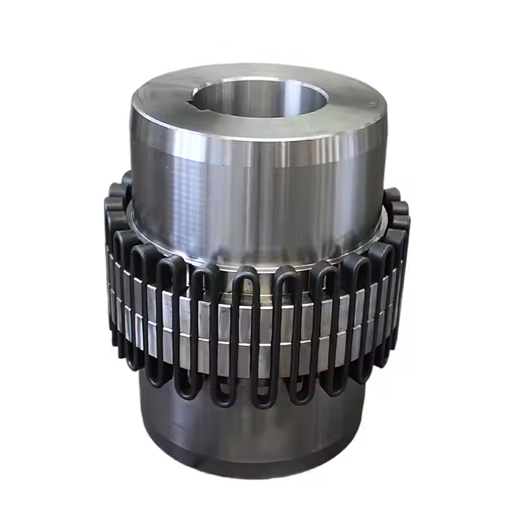
The grid element is the coupling's working member — it flexes under torque and absorbs shock, and it is the component that wears first in normal service. The wear mechanism is contact fatigue at the grid-slot interface: under transmitted torque and misalignment sliding, the contact surfaces work against each other with the EP grease film separating them. Over time the grid cross-section reduces, and the reduced cross-section increases the stress per unit area, accelerating the wear in a feedback loop that ends when the grid fractures or loses the ability to transmit torque.
The early indicator is the drained grease: a grid in normal running-in shows fine steel shimmer; a grid in progressive wear shows coarser metallic particles that increase in size and quantity at each inspection. The vibration at motor-speed frequency also trends upward as the grid cross-section reduces and the coupling's torsional stiffness changes. The prevention action is the scheduled grease inspection and the grid replacement before the cross-section reaches the manufacturer's minimum — a planned element change costs a fraction of an unplanned coupling or driven-equipment failure.
Seal Leakage and Grease Loss
The seals retain the grease and exclude contamination. A seal that leaks — from a nick at installation, from lip wear against a scored shaft, or from hardening at elevated temperature — loses grease and admits the dust or moisture that ends the coupling's life. The failure sequence is straightforward: grease level drops, the grid-slot contact loses lubrication film thickness, wear accelerates, and contamination enters. By the time the leak is visible as grease on the coupling housing, the internal condition has already degraded.
The early indicator is a wet film or seepage at the seal lip, or a falling grease level at the scheduled check. The prevention action is seal inspection at each lubrication interval and seal replacement at the first sign of lip wear or hardening — the seal is a low-cost component whose failure cascades into the grid. For elevated-temperature duties, confirming the seal compound rating against the operating temperature prevents the hardening that causes leakage in the first place.

Lubrication Breakdown
The grid-slot contact operates in a boundary lubrication regime — the combination of load, sliding velocity, and geometry prevents a full hydrodynamic film, so the EP additive in the grease forms the protective layer. Using the wrong grease — non-EP grade, or a thickener incompatible with the duty — removes that protection, and the surfaces begin to adhere and tear at the asperity contacts. Over-filling causes churning and heat; under-filling leaves contact zones starved. Both conditions reduce the film and accelerate wear.
The early indicator is a rising coupling housing temperature above the catalog-specified maximum, or grease that has darkened and lost consistency at the scheduled change. The prevention action is the specified EP grease at the specified fill volume on the specified interval, adjusted for the contamination and temperature of the actual environment rather than the catalog's moderate-condition default. The grease specification is a maintenance decision, not a storeroom default.
Misalignment-Driven Wear
A grid coupling accommodates misalignment, but operation beyond its rated angular or parallel capacity overloads one side of the grid-slot contact, concentrates load at the flank, and thins the lubrication film where the sliding velocity is highest. The wear from chronic misalignment is measurable: couplings found at or beyond rated misalignment at inspection show accelerated grid wear and higher grease contamination than couplings held within roughly half the rated values.
The early indicator is a coupling that heats and wears faster than identical couplings in better-aligned positions, or a vibration trend dominated by the misalignment frequency. The prevention action is the scheduled alignment check — not just at commissioning but at the intervals the application's thermal growth and foundation settlement demand. A coupling aligned once and never re-checked will have drifted, and the drift accumulates wear that subsequent alignment cannot reverse. The alignment requirement is one reason buyers compare grid couplings with flexible coupling alternatives before specifying a drive.
Hub-to-Shaft Fretting
The hub-shaft interface carries the torque through the fit and the key. A clearance-fit hub with a key, on a shaft that sees misalignment-induced prying or frequent starts, can micro-move at the keyway, generating fretting debris that appears as metallic particles in the drained grease and as a slowly rising vibration at motor speed. The fretting is not a grid problem, but it presents as one in the grease inspection and is misdiagnosed accordingly.
The early indicator is fretting debris at the keyway combined with a hub that has moved axially or rotationally on the shaft. The prevention action is the correct fit class for the duty — an interference or clamp-style hub resists the prying moment that causes micro-movement, while a clearance-fit hub with a key alone is the source of fretting in high-misalignment or high-start applications. The fit class is a selection decision made before installation, not a maintenance correction after the fact.
Overload and Peak Torque Exceedance
The grid coupling's peak torque capacity — typically 2.0 to 2.5 times the continuous rating — absorbs the shock events the application produces. An event beyond that capacity, or chronic operation near the peak, plastically deforms the grid and reduces its ability to flex, shifting load to the hubs and seals. A single severe overload can fracture the grid; chronic near-peak operation shortens the element life to a fraction of the design value.
The early indicator is a grid that shows permanent deformation or a coupling that no longer accommodates misalignment after a known jam or stall event. The prevention action is the service factor assignment that sizes the coupling for the application's actual peak — including the jam-start or stall torque, not the running torque alone. The selection that ignores the peak leaves the coupling sized for the average and exposed to the event that ends it.
Inspection Program That Catches the Modes Early
A condition-based inspection program for a grid coupling uses two primary signals: the drained grease condition and the vibration trend. The grease inspection catches grid wear, seal leakage, and lubrication breakdown through particle size, quantity, and consistency. The vibration trend catches misalignment wear, hub fretting, and overload through frequency content and amplitude. Together they convert the coupling's progressive failure modes into scheduled replacements rather than emergencies — the grid element is changed on the planned outage the program identifies, before the failure reaches the driven equipment.
Frequently Asked Questions
What does metallic debris in the drained grease indicate?
Fine steel shimmer is normal running-in; coarse, increasing metallic particles indicate progressive grid wear or hub fretting. The particle size and trend across inspections separate normal from degrading condition. A coupling showing increasing coarse particles should have the grid inspected and the replacement interval advanced before the cross-section reaches the minimum.
Can a leaking seal be repaired without replacing the coupling?
Yes — the seal is a replaceable component, and replacing it at the first sign of lip wear or hardening prevents the grease loss and contamination that follow. The seal should be replaced on the scheduled lubrication interval when wear appears; delaying the seal change allows the cascade into grid wear and lubrication breakdown.
Why does misalignment cause wear even though the coupling accommodates it?
The coupling accommodates misalignment within its rated capacity. Operation beyond the rated angular or parallel value concentrates load at the grid-slot flank, thins the lubrication film where sliding velocity is highest, and accelerates wear. The rated capacity is a limit, not a target — holding alignment within roughly half the rated value extends service life measurably.
How do I know if the coupling was overloaded?
Permanent grid deformation, loss of misalignment accommodation after a known jam or stall, or a fracture indicate overload beyond the peak rating. The prevention is sizing the coupling for the application's actual peak torque — including jam-start and stall events — not the running torque alone. A coupling sized only for running torque is exposed to the peak events the application produces.
Conclusion
The grid coupling fails in a short list of modes, and every mode produces an early indicator a maintenance route can catch. Grid fatigue shows in the grease and the vibration trend. Seal leakage shows at the lip before the grease is gone. Lubrication breakdown shows in the housing temperature and the grease condition. Misalignment wear shows in the differential heating and the vibration frequency. Hub fretting shows in the keyway debris. Overload shows in the grid deformation after the event. The prevention is not a single action but a program: correct fit at selection, correct grease at the correct interval, alignment checks on the application's schedule, and a grease-and-vibration inspection that turns each progressive mode into a planned replacement. A plant that runs this program gets the coupling's design life and avoids the emergency that the same coupling would otherwise become.
References
AGMA 9002-B04 — Flexible Couplings: Design Considerations and Selection
ISO 14691:2008 — Flexible Couplings: Design, Selection and Application
Bloch, H.P. & Geitner, F.K. (2011). Machinery Failure Analysis and Troubleshooting, 4th Edition. Butterworth-Heinemann.
Pai, N. (2015). Practical Machinery Management for Process Plants, 4th Edition. Gulf Professional Publishing.
API 686 — Recommended Practice for Machinery Installation and Installation Design