

The T20 series grid coupling family encompasses a range of models designed to cover industrial power transmission applications from light-duty auxiliary drives to heavy-duty main drive trains. While all T20 series couplings share the fundamental grid spring operating principle — a serpentine steel spring transmitting torque through crowned hub tooth profiles — individual models differ in torque capacity, speed rating, material specifications, and dimensional configurations that determine their suitability for specific applications.
This comparison guide examines the key differences between T20 series grid coupling models, providing selection guidance based on application requirements. Understanding these differences enables engineers and procurement professionals to match the correct model to each installation, optimizing both performance and cost.
T20 Series Model Overview and Size Range
The T20 series grid coupling family includes models designated by numbers that correspond to nominal torque capacity and bore size ranges. Standard T20 models span sizes from T20-1 through T20-12, with each size increment providing approximately 25-35% higher torque capacity than the previous size. The T20-1, rated for the lowest torque range, serves light-duty applications such as small pumps and fans, while the T20-12 handles the highest torque demands of heavy mining and steel mill drives.
Within each nominal size, multiple bore range options accommodate different shaft diameters. A T20-4 coupling, for example, may be available in bore ranges of 1.5-2.5 inches and 2.0-3.0 inches, allowing the same coupling size to serve installations with different shaft dimensions without oversizing. The bore range selection affects the hub wall thickness and consequently influences the coupling's torque capacity within that size class.
Model selection begins with torque requirements but must also consider the available space envelope. T20 series couplings have defined overall lengths, outside diameters, and flange dimensions that vary by size. Installing a coupling that is too large for the available space requires equipment repositioning, while one that is too small may not accommodate the required bore size even if torque capacity appears adequate.
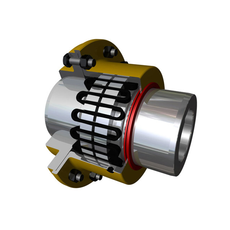
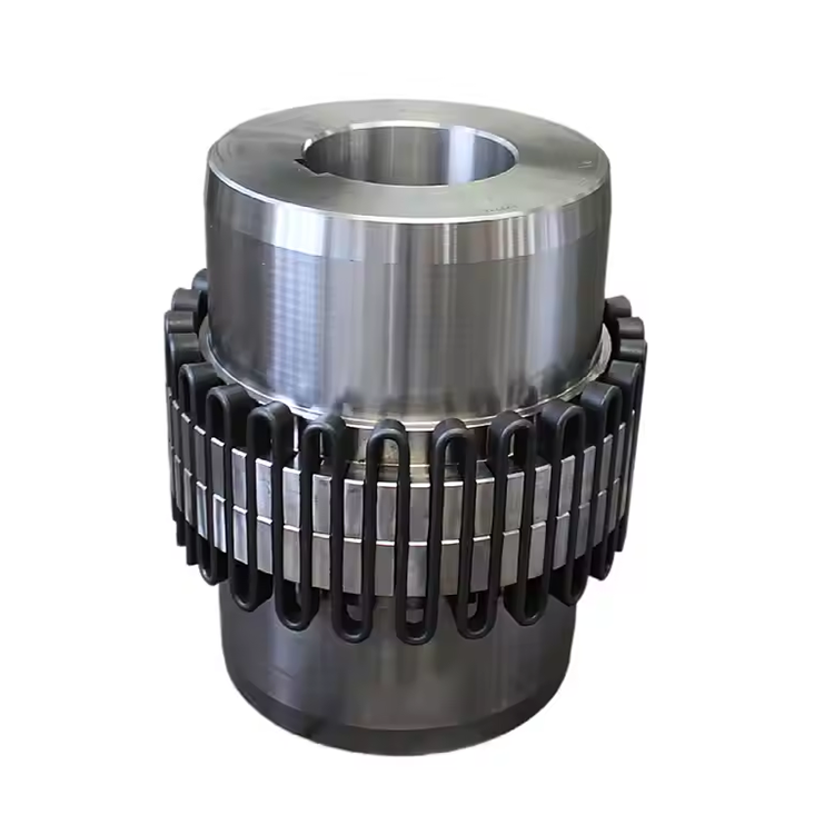
Torque Capacity Comparison Across T20 Models
Torque capacity is the primary differentiator between T20 series grid coupling models. The T20-1 typically provides rated continuous torque of approximately 150 Nm, while the T20-12 exceeds 50,000 Nm in its maximum configuration. This wide range allows the T20 series to cover applications from fractional-horsepower auxiliary drives to multi-megawatt main drive trains using the same coupling family and maintenance procedures.
Service factor application follows the same principles across all T20 models. For uniform load applications — centrifugal pumps, fans, and light conveyors — a service factor of 1.0-1.3 applies. Moderate shock loading — reciprocating compressors, screw conveyors, and agitators — requires 1.5-2.0. Heavy shock loading — crushers, grinding mills, and reversing drives — demands 2.0-3.0. The selected service factor multiplies nominal torque to determine the required model size.
Peak torque capacity for T20 models typically reaches 200-250% of continuous rating for short-duration events. This overload margin provides protection during startup surges, material jam events, and emergency conditions. Models with larger grid cross-sections — particularly T20-6 through T20-12 — exhibit proportionally higher peak-to-continuous ratios because the larger grid segments have greater elastic deflection range before reaching stress limits.
Misalignment Capacity by Model Class
Misalignment capacity varies across T20 series grid coupling models based on hub tooth profile design and grid spring geometry. Standard T20 models provide angular misalignment capacity of 0.75-1.0° per flex plane, parallel offset of 0.010-0.050 inches, and axial displacement of 0.030-0.090 inches for sizes T20-1 through T20-8. Larger models — T20-9 through T20-12 — offer proportionally higher absolute misalignment values, typically 0.050-0.090 inches parallel offset, due to their larger tooth engagement area.
High-misalignment variants within the T20 series — often designated as T20-HM or similar — provide increased misalignment capacity through modified tooth crown profiles and extended grid engagement lengths. These variants offer approximately 50% higher angular misalignment capacity and 30% higher parallel offset capacity compared to standard models of the same size, at the cost of slightly reduced peak torque capacity from the modified tooth profile geometry.
Combined misalignment — angular and parallel offset acting simultaneously — must be considered when comparing models. The combined condition reduces the available capacity in each plane. For installations where both angular and parallel misalignment are present, high-misplacement variants or oversized standard models provide the necessary capacity margin. Coupling manufacturers provide combined misalignment curves for each model in their technical catalogs.
Speed Rating Variations Across the Series
Maximum operating speed varies significantly across T20 series grid coupling models. Smaller models — T20-1 through T20-4 — achieve maximum speeds of 4,000-5,000 RPM due to their smaller diameters, which reduce centrifugal force effects on the grid and cover. Mid-range models — T20-5 through T20-8 — are typically rated for 2,500-3,800 RPM. Large models — T20-9 through T20-12 — are limited to 1,200-2,500 RPM depending on specific configuration.
Speed derating applies when operating near the maximum speed rating. At speeds above 75% of maximum, centrifugal forces can affect grid position within the hub teeth, potentially reducing torque transmission effectiveness. For continuous operation above 75% of rated speed, consult the coupling manufacturer's high-speed guidelines, which may recommend modified grid designs or enhanced balancing specifications.
Balance grade availability varies by T20 model. Standard T20 models are balanced to G6.3 per ISO 21940, suitable for most industrial speeds below 3,600 RPM. Precision balance to G2.5 or G1.0 is available for smaller T20 models (T20-1 through T20-6) where high-speed operation is common. Larger models typically achieve G6.3 as standard, with G2.5 available as a special order for applications requiring enhanced balance quality.
Material and Configuration Options
Grid spring material options differentiate T20 series grid coupling models for specific service conditions. Standard T20 models use high-carbon spring steel — AISI 1070 or 1095 — heat-treated to 45-50 HRC for standard industrial service. Stainless steel grid options — 17-7PH or 301 stainless — are available for corrosive environments including offshore, chemical processing, and food-grade applications where corrosion resistance is essential.
Hub material options include standard AISI 1045 steel for moderate-duty applications and AISI 4140 alloy steel for heavy-duty service requiring higher strength and impact resistance. Cast steel hubs are available for the largest T20 models (T20-9 and above) where cast-to-shape production provides cost advantages over forged or bar-stock construction. Hub material selection affects weight, strength, and cost — factors that must be balanced against application requirements.
Cover configuration options include steel stampings for standard service, cast iron covers for heavy-duty applications requiring enhanced sealing, and stainless steel covers for corrosive environments. Cover sealing ranges from standard labyrinth seals for clean environments to contact seals — lip or O-ring designs — for contaminated or washdown applications. Model selection should account for the available cover and seal configurations, as these affect maintenance intervals and replacement part availability.
Installation and Maintenance Differences
Installation procedures across T20 series grid coupling models follow the same principles but differ in detail based on size and configuration. Small T20 models — T20-1 through T20-4 — use lightweight hubs that can be installed manually with basic tooling. Medium models — T20-5 through T20-8 — require lifting equipment for hub positioning and may need hydraulic tools for interference-fit installation. Large models — T20-9 through T20-12 — require substantial material handling equipment and specialized installation tooling.
Lubrication requirements vary by T20 model size and speed. Small models operating at moderate speeds accept standard NLGI Grade 1 semi-fluid grease. Large models or high-speed applications may require Grade 0 grease for improved flow characteristics and churning resistance. Grease fill quantities scale with coupling volume — T20-1 requires approximately 0.2 liters, while T20-12 may exceed 5 liters per coupling — affecting both initial fill cost and ongoing replenishment expense.
Spare parts inventory requirements differ across T20 model sizes. Grid springs — the most frequently replaced component — are model-specific and not interchangeable between different T20 sizes. Facilities operating multiple T20 sizes should maintain grid spare inventory for each model in service, while those with a single T20 size minimize inventory complexity. Hub interchangeability within T20 series sizes is limited by bore range — hubs from different T20 models cannot be mixed in the same coupling assembly.
Frequently Asked Questions
What is the difference between T20-4 and T20-5 models?
The primary difference is torque capacity — a T20-5 provides approximately 30-35% higher rated torque than a T20-4. The T20-5 also has larger maximum bore capacity, higher misalignment capacity, and different dimensional envelope. Selecting between them is determined by the application's torque requirement after applying the appropriate service factor — if the adjusted torque falls between these two models, choose the larger T20-5 for margin.
Can I use a T20-3 grid in a T20-4 hub?
No. Grid springs are model-specific and sized for the tooth profile and spacing of their corresponding hub assembly. Installing an undersized grid in a larger hub results in improper tooth engagement, reduced torque capacity, and accelerated grid wear. Always use the grid spring specified for the exact T20 hub model in use.
Which T20 series grid coupling model is best for high-speed applications?
Smaller T20 models — T20-1 through T20-4 — are best suited for high-speed applications because their smaller diameters reduce centrifugal forces on the grid and cover. These models achieve maximum speeds of 4,000-5,000 RPM, compared to 1,200-2,500 RPM for larger models. For sustained high-speed operation above 3,600 RPM, specify precision balance (G2.5 or higher) and consider high-speed cover configurations.
How do I choose between standard and stainless steel T20 grid options?
Choose standard carbon steel grids for dry, indoor, or controlled environments where corrosion is not a significant concern. Choose stainless steel grids for outdoor installations, washdown environments, chemical processing, food-grade applications, or any service where moisture or corrosive agents contact the coupling. The stainless option typically costs 40-60% more but provides 3-5 times longer service life in corrosive conditions.
Conclusion
Comparing T20 series grid coupling models requires evaluating torque capacity, misalignment accommodation, speed rating, material options, and dimensional characteristics against the specific demands of each application. The T20 series provides a well-structured range of models that cover light-duty through heavy-duty industrial applications with standardized maintenance procedures and replacement parts within each size class. Engineers who systematically evaluate these parameters — applying appropriate service factors, verifying speed and misalignment compatibility, and selecting appropriate material grades — consistently achieve reliable coupling performance and lowest total cost of ownership across their T20 series installations.
References
AGMA 9002-B04 — Flexible Couplings: Design Considerations and Selection
ISO 14691:2008 — Flexible Couplings: Design, Selection and Application
Mancuso, J.R. (1999). Couplings and Joints: Design, Selection, and Application, 2nd Edition. Marcel Dekker.
API 671 — Special Purpose Couplings for Petroleum, Chemical, and Gas Industry Services
ISO 21940-11:2016 — Mechanical Vibration: Rotor Balancing