

Among the various flexible coupling designs used in heavy industrial power transmission, the grid coupling stands out for its combination of high torque capacity, torsional flexibility, and shock load absorption. However, like any mechanical component operating under demanding conditions, grid couplings experience characteristic failure modes that — if left unaddressed — lead to unplanned downtime, equipment damage, and costly production interruptions.
Based on field service data collected across mining, pulp and paper, steel processing, and petrochemical applications, this article identifies the most common grid coupling problems encountered in industrial service and provides proven troubleshooting approaches that maintenance teams can implement immediately.
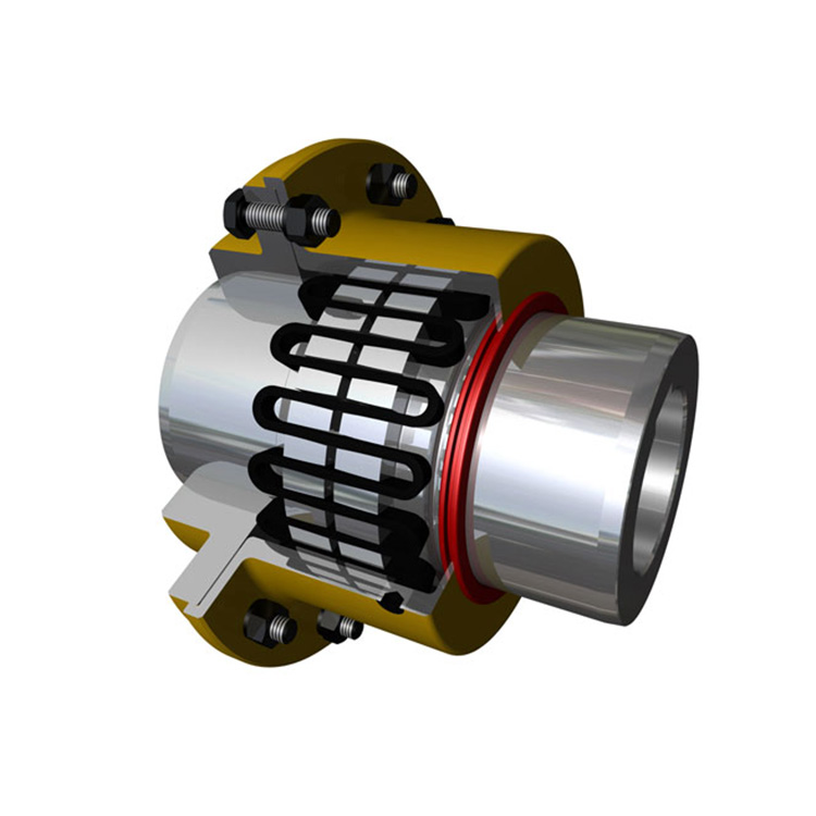
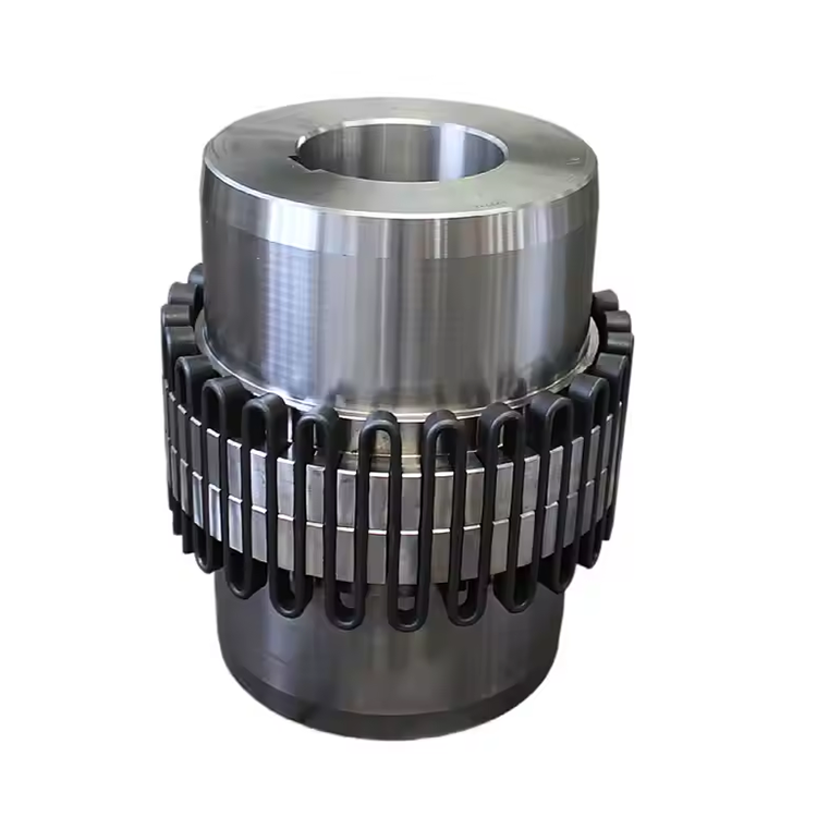
Grid Wear and Fatigue: The Most Frequent Failure Mode
Grid wear ranks as the single most prevalent reason for grid coupling replacement in industrial applications. The grid element — typically a spring steel or stainless steel serpentine segment — experiences continuous cyclic loading as it flexes within the hub tooth profile during each rotation. Over thousands of operating hours, this repeated flexing produces surface fatigue that progressively reduces grid cross-section and weakens the coupling assembly.
Operators typically detect grid wear through vibration analysis trending. As the grid thins, backlash within the coupling increases, producing characteristic 1X and 2X vibration harmonics at frequencies corresponding to shaft rotation speed. When vibration amplitudes exceed baseline values by 30-50%, grid inspection and probable replacement should be scheduled at the next available outage window.
Preventive grid replacement based on operating hour intervals — rather than failure-driven replacement — significantly reduces unplanned downtime. Most grid coupling manufacturers publish recommended replacement intervals based on load severity classifications. Following these guidelines typically extends mean time between coupling-related failures by 40-60% compared to run-to-failure strategies.
Lubrication Breakdown: Causes, Symptoms, and Prevention
Proper lubrication is absolutely essential for grid coupling longevity. The lubricant serves two critical functions: reducing friction between the grid and hub teeth during flexing, and protecting exposed metal surfaces from corrosion in the coupling housing. When lubrication breaks down, both grid wear rates and corrosion risks increase dramatically.
Lubrication failure typically results from one of three causes: incorrect lubricant selection, inadequate lubrication intervals, or contamination ingress. Using a lubricant with insufficient load-carrying capacity or poor water resistance leads to accelerated grid wear and tooth surface pitting. Plants operating in humid or washdown environments must specify couplings with sealed covers and water-resistant grease formulations.
The most reliable indicator of lubrication health is periodic grease sampling during scheduled inspections. Fresh grease should appear clean and homogeneous with the original color and consistency. Discolored, gritty, or separated grease indicates degradation requiring immediate replenishment. Many reliability-focused facilities have adopted quarterly grease analysis programs for their critical grid coupling installations, catching lubrication issues before equipment damage occurs.
Misalignment-Induced Stress on Grid Coupling Components
While grid coupling designs accommodate moderate shaft misalignment through grid flexibility, operating beyond rated misalignment limits produces disproportionate stress on both the grid element and hub tooth profiles. The grid experiences localized bending at overload points, creating stress concentrations that accelerate fatigue crack initiation.
Hub tooth wear patterns provide valuable diagnostic information about alignment conditions. Uneven wear concentrated on one side of the tooth profile indicates angular misalignment, while uniform but accelerated wear across all teeth suggests parallel offset combined with torsional overload. Maintenance technicians should photograph and document tooth wear patterns during each inspection to build trend data supporting predictive replacement scheduling.
Coupling manufacturers publish maximum allowable misalignment values for each model and size. These values assume proper lubrication, normal load conditions, and operation within rated speed range. Exceeding any of these parameters requires derating the coupling's misalignment capacity proportionally. Operations experiencing chronic misalignment-related grid failures should conduct a thorough shaft alignment survey using laser measurement equipment to identify and correct the root cause.
Vibration and Noise: Early Warning Indicators
Elevated vibration and unusual noise are often the first observable symptoms of developing grid coupling problems. A healthy grid coupling operates with relatively low vibration amplitude — typically below 0.1 inches per second velocity in the frequency range associated with coupling harmonics. Significant increases in these readings signal deterioration requiring investigation.
Characteristic noise patterns help distinguish between failure modes. A metallic rattling or clicking sound during startup or speed changes typically indicates excessive grid backlash from wear. A continuous high-pitched whine suggests inadequate lubrication causing grid-to-tooth dry contact. Low-frequency knocking or thumping often points to hub tooth damage or loose fits between the grid and hub profiles.
Vibration monitoring programs utilizing permanently mounted accelerometers provide the earliest detection of coupling deterioration. These systems can detect changes in vibration signature weeks or months before audible symptoms become apparent, enabling planned maintenance interventions that avoid emergency shutdowns.
Corrosion and Environmental Damage
Industrial environments expose grid coupling assemblies to moisture, chemicals, and airborne particulates that accelerate corrosion and component degradation. Corrosion weakens the grid element by reducing effective cross-section, while simultaneously damaging hub tooth surfaces and cover seal integrity.
Facilities in coastal, tropical, or regularly washed-down environments face the greatest corrosion challenges. Standard carbon steel grid couplings in these applications may require stainless steel grid elements and corrosion-resistant cover coatings to achieve acceptable service life. Rubber or polymer sealing boots on the coupling cover significantly reduce moisture and contaminant ingress when properly maintained.
Post-corrosion inspection protocols should include visual examination of all exposed surfaces, measurement of grid cross-section at multiple points using digital calipers, and assessment of hub tooth surface condition. Any grid showing cross-section reduction exceeding 15% of original dimension should be replaced regardless of operating hours.
Troubleshooting Quick-Reference Checklist
When a grid coupling problem is suspected, a systematic troubleshooting approach isolates the root cause faster than random component replacement. Start with vibration data analysis to characterize the failure mode. Check lubrication condition and quantity. Inspect the grid for visible wear, cracking, or corrosion. Examine hub tooth profiles for uneven wear or pitting. Verify shaft alignment using a laser measurement system. Finally, confirm that the coupling is correctly sized for the application's torque and speed requirements.
Documenting each troubleshooting step creates valuable institutional knowledge that speeds future diagnostics and supports data-driven decisions about coupling upgrades or replacements. Maintenance teams that maintain detailed coupling inspection records typically resolve problems 50-70% faster than those relying on individual technician memory.
Frequently Asked Questions
How do I know when my grid coupling grid needs replacement?
The primary indicators are increased vibration at coupling harmonic frequencies, visible grid wear or cracking during inspection, and increased backlash detected during manual rotation checks. Most manufacturers recommend grid replacement when cross-section reduction reaches 15-20% of original dimensions, or at published operating hour intervals — whichever occurs first.
What type of lubricant should I use for a grid coupling?
Use a high-quality coupling grease with EP (extreme pressure) additives and good mechanical stability. NLGI Grade 1 or 2 consistency is typical, depending on speed and operating temperature. Consult the coupling manufacturer's lubrication guide for specific recommendations. Never mix grease types, as incompatibility between formulations can cause softening, separation, or loss of lubricating properties.
Can a grid coupling operate with some shaft misalignment?
Yes — within rated limits. Grid couplings are specifically designed to accommodate limited angular and parallel misalignment through grid flexibility. However, operating near or beyond the rated misalignment capacity significantly reduces grid fatigue life. Precision laser alignment to within manufacturer tolerances ensures the coupling's misalignment compensation capability remains available for residual and dynamic misalignment during operation.
What causes a grid coupling to run hot?
Excessive heat generation typically results from inadequate lubrication, over-torque loading, or excessive misalignment forcing the grid to flex beyond its designed amplitude. Check lubrication condition and quantity first, then verify operating torque against coupling rated capacity, and finally conduct a shaft alignment check. Operating temperatures above the lubricant's maximum rated temperature accelerate grease degradation and create a self-reinforcing failure cycle.
Is it possible to over-grease a grid coupling?
Yes. Over-greasing pressurizes the coupling cover, potentially forcing grease past the seals and onto surrounding equipment. It can also create churning losses that generate excess heat. Follow the manufacturer's recommended fill quantity — typically 50-75% of available cover volume, depending on coupling size and speed. Always leave adequate void space for grease displacement during operation.
Conclusion
Understanding the common failure modes of grid coupling assemblies empowers maintenance teams to implement effective prevention strategies that minimize unplanned downtime and reduce total ownership costs. The majority of grid coupling problems — lubrication breakdown, misalignment-induced stress, corrosion, and wear — are detectable through routine inspection and vibration monitoring well before catastrophic failure occurs. A disciplined approach to preventive maintenance, guided by manufacturer recommendations and supported by field data, transforms the grid coupling from a recurring reliability concern into a predictable, long-service-life component that delivers consistent performance across demanding industrial applications.
References
AGMA 9002 — Flexible Couplings: Design and Selection
ISO 14691 — Flexible Couplings for Mechanical Power Transmission
Brasel, J.N. (2010). "Failure Analysis of Grid Couplings in Heavy-Duty Applications." Journal of Mechanical Design, 132(8), 081001.
API 671 — Special Purpose Couplings for Petroleum, Chemical, and Gas Industry Services
Soh, Y. et al. (2018). "Wear Mechanisms in Metallic Flexible Couplings Under Cyclic Loading." Wear, 398-399, 46-58.