

Selecting a coupling is a discipline of checks, not a single calculation. The torque calculation comes first, then the service factor, then the speed check, then the bore verification, then the misalignment confirmation. Each step eliminates a failure mode, and skipping a step is how couplings end up undersized, mismatched to the application, or installed with insufficient bore for the shaft. This article walks through the T20 series grid coupling selection sequence in the order that the decisions actually have to be made, with the calculations that determine each decision and the application logic that assigns the right numbers.
Step 1: Calculate the Actual Running Torque
The nameplate power and speed on the motor nameplate give the nominal torque, but not the actual running torque. Actual torque comes from measured or estimated power at the coupling location — which may be lower than nameplate if the motor is not fully loaded, or higher if the driven machine operates above its rated duty. The basic torque calculation is straightforward: convert kilowatts or horsepower to torque using the speed. For a 75 kilowatt motor at 1,780 RPM, the nominal torque is approximately 403 Newton-meters. For a 100 horsepower motor at 1,200 RPM, it is approximately 592 Newton-meters.
The critical question is whether the motor runs at full nameplate power continuously. In many industrial applications — pumps, fans, conveyors — the motor runs at partial load for significant periods. A T20 series grid coupling sized for full nameplate torque when the actual running torque is 60% of nameplate will be oversized, which is not harmful but may cost more than necessary. A coupling sized for partial-load torque when the machine occasionally runs at full load will be undersized, and the grid element will show the wear of overload before its design life ends. The conservative approach is to size for the maximum torque the machine will actually transmit, even if only intermittently.
Step 2: Assign the Service Factor
The service factor converts nominal torque to selection torque — the torque value the coupling must transmit continuously without damage. It accounts for the severity of the driven machine's load, the frequency and nature of shock events, and the number of starts per hour. The T20 series grid coupling catalog provides service factor tables organized by driven machine type and driver type, and the selection torque is the nominal torque multiplied by the service factor.
The service factor for a driven fan or pump with uniform load is typically 1.0 to 1.5. For a conveyor with moderate shock, 1.5 to 2.0. For a crusher, hammer mill, or heavy reciprocating compressor with severe shock, 2.0 to 2.5. The assignment is not arbitrary — it reflects the torque amplification the coupling will experience in service. A crusher that jams and stalls generates torque spikes of 200-300% above running torque, and the T20 series grid coupling's peak torque capacity is rated precisely for these events. But if the coupling is selected at only the running torque with a service factor of 1.0, the grid is sized for running torque and the peak torque events exceed its capacity — the grid deflects beyond its working range, and the accumulated plastic deformation shortens the element life to a fraction of the design value.
Step 3: Check the Speed Rating
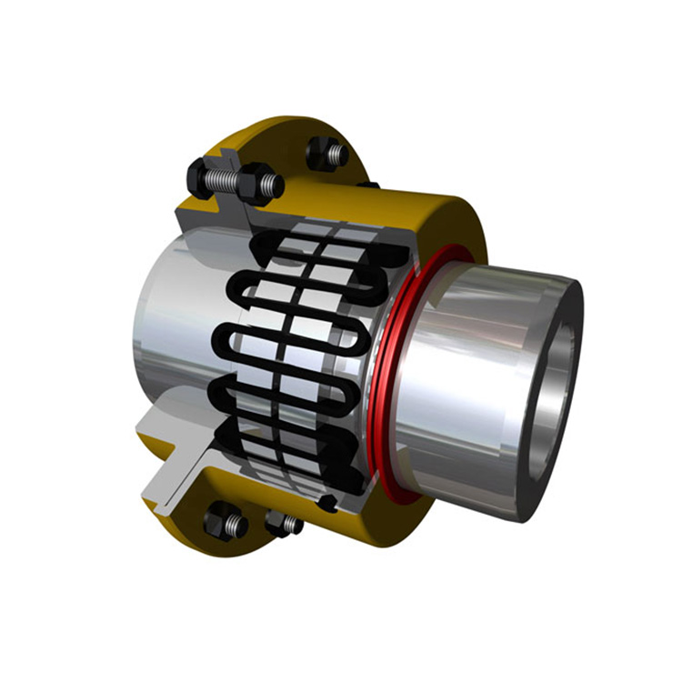
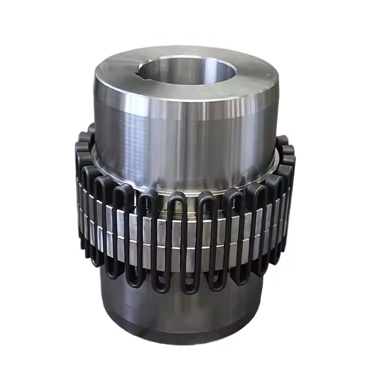
Every T20 series grid coupling size has a maximum RPM rating independent of its torque rating. This rating comes from the centrifugal stress on the grid element at speed, the balance quality of the rotating assembly, and the seal lip speed at the housing perimeter. The speed check is often the step that determines the final size, particularly for machines running at 1,750 or 3,600 RPM where the speed rating of the coupling sized for torque may be at or near its limit.
The selection sequence is: calculate selection torque, identify the smallest T20 series size that meets or exceeds the selection torque at the operating speed, then verify that this size's speed rating exceeds the application's maximum operating speed with margin. If the speed check fails — the size that meets the torque requirement is rated below the operating speed — the next larger T20 series size must be selected, which also increases the bore range and may resolve the fit issue on the shaft. A coupling selected on torque alone and then found to be below speed rating at the job site causes an ordering delay and a production loss that the extra engineering time at the front end would have prevented.
Step 4: Verify Bore and Keyway Compatibility
The bore range of the selected T20 series grid coupling size must include the actual shaft diameter with appropriate fit. For a standard commercial shaft to ISO metric tolerances, the bore fit is typically H7/h6 or similar transition fit, which allows assembly without heating while providing adequate location for torque transmission. For a precision application or a shaft with standard ANSI keyway dimensions, the fit class may require verification against the coupling manufacturer's bore tolerance tables.
The keyway dimensions must match both the shaft keyway and the applicable standard — ISO 773 for metric shafts, ANSI B17.1 for inch shafts. A T20 series grid coupling hub that fits the shaft diameter but has a keyway machined to the wrong standard class will have a keyway that is too wide or too narrow for the shaft key, producing the fretting and key-rock failure modes described in the installation literature. The bore and keyway are specified together as part of the coupling order, and the supplier's engineering confirmation of feasibility is the step that catches mismatches before manufacturing.
Step 5: Confirm Misalignment Capacity Matches the Application
The T20 series grid coupling provides rated angular and parallel misalignment values in its catalog data. These are maximum values — the coupling can operate at these levels without immediate damage, but not without wear acceleration. For the selection, the question is whether the application will keep alignment within approximately 50% of the rated values during operation. If the driven machine is on a flexible foundation, subject to significant pipe strain, or operates over a wide temperature range where thermal growth is substantial, the as-found alignment at the worst operating condition should be estimated and compared to the coupling's rated capacity.
A T20 series grid coupling selected for torque, speed, and bore, but with a misalignment requirement that exceeds its rated angular capacity, will fail at the tooth mesh or the grid slot before the design life is reached. In these cases, the coupling size may need to increase to access a larger coupling's higher misalignment rating, or the installation design must be improved to reduce the misalignment the coupling will actually see.
Step 6: Specify Lubrication and Environmental Conditions
The T20 series grid coupling uses EP (extreme pressure) grease as the standard lubricant, with fill volumes specified per coupling size. For standard indoor industrial environments with temperatures between approximately minus 20 and plus 60 degrees Celsius, the standard grease specification is adequate. For environments outside this range — hot mill drives, outdoor installations in freezing climates, food-industry washdown — the grease specification and potentially the seal compound must be adjusted from the standard configuration.
Seal material options for the T20 series typically include nitrile rubber for standard temperatures and fluoroelastomer (FKM) for elevated temperatures. The seal specification is part of the selection, not an afterthought, and it should be confirmed with the supplier based on the actual operating temperature range and any chemical exposure from the surrounding process.
Step 7: Document the Specification and the Duty Summary
The complete T20 series grid coupling specification — size, bore and fit class, keyway standard, seal material, grease specification, and quantity — belongs in the machine documentation alongside the motor data, the driven machine duty summary, and the alignment targets. This documentation is the basis for the procurement order, the receiving inspection criteria, and the maintenance schedule. Without a written duty summary, the next person who touches the coupling order has no basis for confirming that the selection is still correct for the application.
A specification that names only the coupling size and bore — without the duty summary, the service factor, or the environmental conditions — is a procurement order, not an engineering specification. The difference matters when the coupling is re-ordered in two years by a buyer who does not know the service conditions and substitutes a standard configuration for the application's required seal material or grease grade.
Frequently Asked Questions
What comes first in T20 series grid coupling selection: torque or speed?
Torque comes first to identify candidate sizes, then speed is checked against each candidate's rating. The size that meets torque may fail the speed check, pushing the selection to the next larger size. Both checks must pass before the size is confirmed.
How do I choose the service factor for a T20 grid coupling?
Use the coupling manufacturer's service factor table, which categorizes driven machines by load type — uniform, moderate shock, heavy shock, severe shock. The driver type — electric motor, diesel engine, turbine — also affects the factor. Assign the factor based on the worst-case duty the machine will actually experience, not the typical operating condition.
Can I use the T20 series grid coupling above its rated speed with a smaller torque load?
No. The speed rating is a hard limit derived from centrifugal stress on the grid and balance quality — it is not adjustable based on torque load. Operating above the rated speed risks grid fatigue and seal failure regardless of the torque transmitted.
What if the shaft diameter falls between the minimum and maximum bore of the selected T20 size?
The coupling hub can be machined to the required bore within the size's bore range. Confirm the bore machining capability with the supplier — some manufacturers machine to order, others hold standard bores. Custom bores may extend the lead time and should be factored into the project schedule.
How often does a T20 series grid coupling need lubrication?
For standard indoor service, every 6 to 12 months depending on speed and contamination level. Harsher environments — dusty, hot, or humid — require shorter intervals. The lubrication interval is set by the actual operating conditions, not the catalog's maximum interval, which assumes clean and moderate conditions.
Conclusion
How to select the right T20 series grid coupling is a sequence of engineering checks, not a single torque calculation. Running torque and peak torque establish the selection torque with the service factor. Speed verification ensures the selected size does not exceed its RPM limit. Bore and keyway confirmation prevents installation problems. Misalignment capacity is checked against the application's actual alignment drift. Lubrication and environmental specifications are matched to the operating conditions. And the complete specification — including the duty summary — is documented for procurement, inspection, and maintenance. A plant that follows this sequence gets a coupling that survives its application, and a maintenance team that has the specification it needs to reorder correctly when the time comes.
References
AGMA 9002-B04 — Flexible Couplings: Design Considerations and Selection
ISO 14691:2008 — Flexible Couplings: Design, Selection and Application
ISO 773:2007 — Rectangular or Square Parallel Keys and Their Corresponding Keyways
Mancuso, J.R. (1999). Couplings and Joints: Design, Selection, and Application, 2nd Edition. Marcel Dekker.
Bloch, H.P. & Geitner, F.K. (2011). Machinery Failure Analysis and Troubleshooting, 4th Edition. Butterworth-Heinemann.