

A long distance conveyor is not simply a longer version of a short conveyor. The mechanical dynamics change qualitatively when the conveyor spans hundreds of meters or even several kilometers. Multiple drive stations introduce complexity in torque distribution. Thermal expansion of the belt and structure creates forces that propagate through the entire system. Belt tension variations during startup, running, and stopping create dynamic loads that stress every mechanical connection in the drive train — including the coupling.
In this environment, the choice of Industrial Grid Coupling over alternative coupling types is not merely conventional wisdom — it is an engineering conclusion that follows directly from the unique demands of multi-drive, high-torque, long-span conveyor systems. Understanding why grid couplings are specified in this application and how to ensure they perform as expected over their operational life is the purpose of this guide.
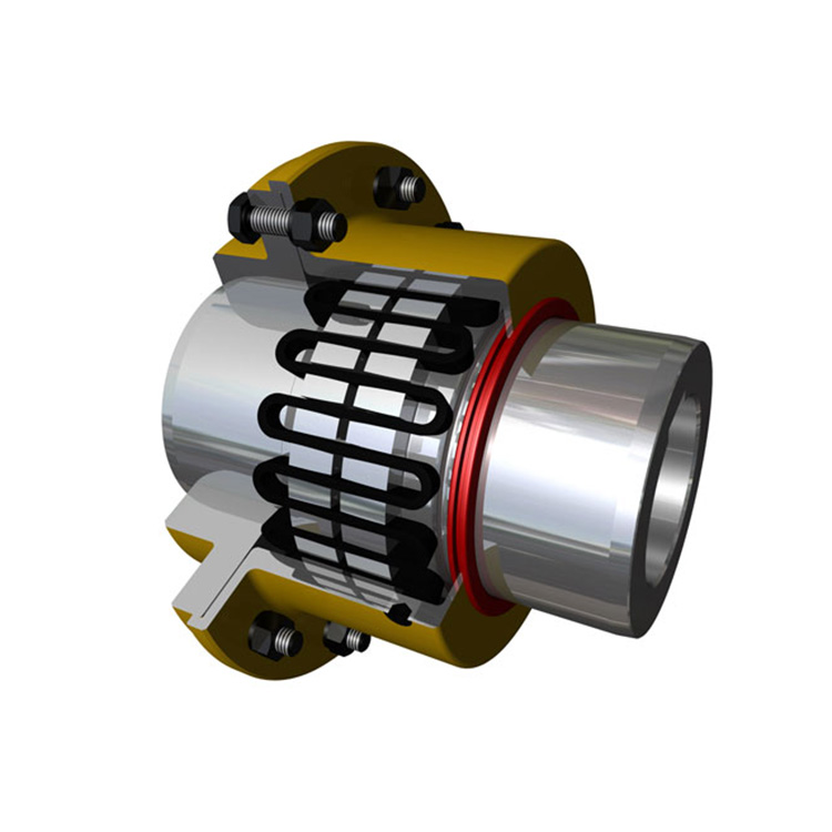
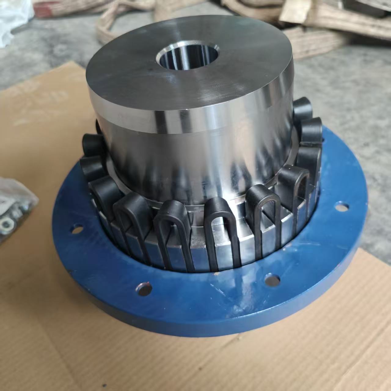
1. Why Grid Couplings Dominate Long Distance Conveyor Applications
Three mechanical characteristics make Industrial Grid Coupling the preferred solution for Long Distance Conveyors: superior torque density, wide misalignment accommodation, and built-in torsional shock absorption.
Torque density — the torque capacity per unit of outside diameter — is higher in grid couplings than in jaw, disc, or gear couplings of comparable size. This is a direct consequence of the grid element's load distribution mechanism: torque is transmitted across the entire surface area of the grid slot rather than at a single point of contact. The result is a coupling that can transmit the 10,000–50,000 Nm torques common in Long Distance Conveyors from a single drive motor while fitting within the same envelope as a smaller, less capable alternative.
Misalignment accommodation is critical in Long Distance Conveyors because the drive station alignment is never perfectly stable. Conveyor frames deflect under belt tension loads, foundations settle over time, and thermal expansion during operation shifts shaft positions by 0.2–0.8 mm depending on the temperature differential and shaft length. An Industrial Grid Coupling with ±0.5 mm parallel offset and ±1.5° angular capacity provides a safety margin that absorbs these real-world variations without accelerated wear.
Torsional vibration damping is inherent in the grid element's sliding action within the hub slots. As torque increases, the grid flanks load against the slot walls and dampen torsional oscillations from motor starting currents, gear reducer tooth meshing, and belt splice impacts. This damping function reduces dynamic loads throughout the drive train, extending the life of gearboxes, motors, and conveyor pulleys.
2. Sizing an Industrial Grid Coupling for Conveyor Drive Duty
Sizing a coupling for a conveyor drive is not a single-calculation process. The starting point is motor nameplate data — rated power and speed — which gives the nominal torque. But nominal torque is the least interesting number in the specification. The engineer needs the service torque, which accounts for motor starting current, belt slip during startup, and any temporary overload conditions.
The standard approach for Long Distance Conveyors is to apply a service factor of 1.5–2.5 to the calculated nominal torque. A conveyor operating at steady state under 8,000 Nm nominal torque, with a motor starting current ratio of 6:1, requires a coupling rated for at least 1.5 × 8,000 = 12,000 Nm — and more conservatively, 2.0 × 8,000 = 16,000 Nm if the conveyor has a history of difficult start-up conditions such as frozen idlers or belt splice slippage.
Beyond torque, the sizing check list for Industrial Grid Coupling selection includes maximum bore capacity (shaft diameter plus keyway), operating speed relative to the coupling's critical speed rating, and temperature at the coupling location (typically elevated by proximity to the drive motor or gear reducer).
3. The Critical Role of Proper Installation in Conveyor Applications
Installation quality is the single largest variable in Industrial Grid Coupling service life. A grid coupling installed with 0.3 mm parallel misalignment instead of the achievable 0.05 mm will still function — but its fatigue life will be approximately 40–60% of the designed value. Over the 25,000-hour service life typical of a Long Distance Conveyors drive, this means the difference between four years of reliable service and a failure-driven replacement in under two years.
The installation sequence for conveyor drive Industrial Grid Coupling follows a well-established protocol. First, verify shaft dimensions, keyway dimensions, and shaft-to-shaft distance against the coupling specification. Second, assemble the coupling halves on their respective shafts before applying any bolt preload — this allows free adjustment of angular and parallel position. Third, perform laser alignment to achieve ±0.05 mm parallel and ±0.1 mm angular alignment. Fourth, verify shaft end-float (axial movement) is within the coupling's axial travel capacity. Fifth, apply the specified bolt preload using a calibrated torque wrench — typically 70–85% of bolt yield strength, cross-tightened in a star pattern.
The final and most frequently skipped step is documenting the installation alignment baseline. Photograph the dial indicator readings, record the coupling hub-to-hub dimension, and store this data in the equipment history file. This baseline enables meaningful comparison at future inspections and eliminates debate about what "acceptable" alignment was at installation.
4. Lubrication Management for Overland and In-Plant Conveyors
The Industrial Grid Coupling in a Long Distance Conveyors application requires regular lubrication — and in this context, "regular" means based on operating hours, not calendar time. A conveyor that runs 24 hours per day, 365 days per year accumulates 8,760 operating hours annually. Grease intervals calculated on a calendar basis (every six months) will result in 4,380 hours of operation between grease services — acceptable. But for a conveyor that runs intermittently, calendar-based greasing may result in over-greasing or under-greasing relative to actual need.
The correct approach is hour-meter-based lubrication scheduling. Modern conveyor control systems can trigger lubrication service reminders based on operating hours logged by the drive motor starter. For Industrial Grid Coupling applications, the standard recommendation is grease injection at 2,000–4,000 hour intervals for standard duty, and 1,000–2,000 hour intervals for heavy-duty applications with high dust exposure or high ambient temperatures.
The grease specification matters equally: lithium-complex EP (extreme pressure) grease with NLGI Grade 2 consistency is the industry standard for grid coupling applications. The EP additive package prevents metal-to-metal contact under high局部压力 conditions when the grid is loaded against the hub slot — a condition that occurs momentarily during every torque peak. Using non-EP grease in high-load Industrial Grid Coupling applications has been documented to reduce grid fatigue life by 25–40% in accelerated life testing.
5. Common Failure Modes and Their Field Indicators
Understanding how Industrial Grid Coupling components fail in Long Distance Conveyors enables targeted inspection protocols that catch degradation early.
Grid fatigue cracking typically initiates at the root of the grid slot where stress concentration is highest. Early detection is possible by visual inspection through the coupling's inspection cover: look for any visible cracks perpendicular to the grid axis, discoloration from heat cycling, or permanent deformation (sagging or flattening of the grid teeth). Once a grid crack is identified, replacement should be scheduled within the next available planned outage — not deferred for weeks.
Bolt preload loss in the flange connection is a gradual process driven by vibration and thermal cycling. Loose bolts produce a characteristic low-frequency vibration signature that vibration analysts learn to recognize. Field crews can check bolt torque with a torque wrench and compare against the original installation torque recorded in the equipment history. A drop of more than 10% from installation torque warrants retightening and investigation of the cause.
Seal degradation allows contamination entry and grease loss. In dusty Long Distance Conveyors — especially overland conveyors in mining and quarrying — seal inspection should be part of every quarterly inspection. Worn or cracked seals should be replaced immediately, as they are the primary defense against the dust and abrasive particles that accelerate grid wear by an order of magnitude.
6. Grid Coupling Selection Criteria for Multi-Drive Conveyor Systems
Long Distance Conveyors frequently use multiple drive stations to manage belt tension and power distribution across very long spans. A conveyor with three 500 kW drive stations at 30%, 30%, and 40% power distribution requires three separate Industrial Grid Coupling installations, each matched to its respective motor-gearbox output shaft.
When specifying couplings for multi-drive systems, ensure all couplings in the system have compatible performance envelopes — consistent misalignment capacity, consistent temperature ratings, and consistent lubrication specifications. Mixing coupling types or coupling brands in a multi-drive system complicates maintenance training, parts inventory, and inspection consistency. Many operations standardize on a single T20 Grid Coupling Supplier across all drive stations specifically to simplify these logistics.
Conclusion
The Industrial Grid Coupling is not merely a connection between the motor shaft and the gearbox shaft in a Long Distance Conveyors application — it is an active mechanical component that accommodates misalignment, dampens vibration, transmits torque, and protects more expensive equipment throughout the drive train. Treating it as an afterthought in the specification process or as a commodity in the procurement process leads directly to the chronic coupling reliability problems that plague too many conveyor operations.
The path to reliable coupling performance in Long Distance Conveyors runs through three gates: correct specification using full engineering data (torque, speed, bore, misalignment, temperature), precision installation with documented baseline alignment, and disciplined hour-based maintenance with correct grease specification and regular element inspection. Each gate adds marginal cost but multiplicative value in extended service life and reduced unplanned downtime. The most cost-effective investment in a conveyor drive train is not the coupling itself — it is the engineering time spent getting the specification and installation right.
Frequently Asked Questions (FAQ)
Q1: Why is the Industrial Grid Coupling preferred over gear coupling for long distance conveyor drives?
Both coupling types are used successfully in Long Distance Conveyors, but they serve different niches. Gear couplings require lubrication (oil or grease) and have limited misalignment tolerance — making them more sensitive to the alignment variations that occur in long conveyor structures. Industrial Grid Coupling designs require minimal greasing, accommodate significantly more misalignment, and provide torsional damping that gear couplings lack. For multi-drive Long Distance Conveyors where alignment stability between maintenance intervals cannot be guaranteed, the grid coupling's forgiving nature is a significant operational advantage.
Q2: How do I calculate the correct service factor for a conveyor Industrial Grid Coupling?
Service factor calculation for Long Distance Conveyors begins with the conveyor type classification. A uniformly loaded, single-start conveyor with no unusual conditions typically uses a service factor of 1.5. Conveyors with high start-stop frequency, significant elevation change, or known difficult start conditions (heavy belt, worn idlers) should use 1.8–2.0. The most conservative approach — appropriate for conveyors with frequent overload events, severe duty cycles, or where coupling failure cost is extremely high — applies 2.5. When in doubt, err toward the higher service factor; the cost difference between a 1.5 and 2.0 rated coupling is small relative to the cost of a coupling failure in a critical Long Distance Conveyors application.
Q3: What is the maximum operating temperature for a standard Industrial Grid Coupling?
Standard Industrial Grid Coupling designs with steel grid and cast iron or steel hubs are rated for continuous operation up to approximately 120°C at the coupling. For Long Distance Conveyors in hot environments (cement, steel, glass industries), the coupling's actual operating temperature should be measured during a representative operating cycle with a contact thermometer or infrared camera before finalizing the specification. High-temperature versions using alloy steel grids and heat-resistant seals extend the rating to 180–200°C — available from specialized T20 Grid Coupling Supplier manufacturers.
Q4: How do multi-drive conveyors affect coupling selection?
In a multi-drive Long Distance Conveyors system, the Industrial Grid Coupling at each drive station must handle the specific torque contribution of that drive motor, not the total system torque. Each coupling is sized individually based on its motor's rated torque and the power share allocated to that drive station. Additionally, the drive control sequence (which drive starts first, whether drives are synchronized) creates unique torsional dynamics at each coupling that may differ from a single-drive installation. Working with the conveyor OEM's drive-train engineering team during specification ensures all coupling selections account for these system-level dynamics.
Q5: What spares should be kept on hand for a critical long distance conveyor coupling?
For a critical Long Distance Conveyors installation, the minimum recommended spare parts inventory for Industrial Grid Coupling support includes one complete spare coupling assembly per drive station, or alternatively two spare grid elements per coupling (allowing one complete replacement plus a spare for planned maintenance). Seal kits, gasket kits, and a grease cartridge for the specified lubricant should be stocked regardless of which approach is chosen. For operations with multiple identical conveyors, standardizing on one T20 Grid Coupling Supplier across all units allows shared inventory of these spares across the operation.
References:
Pimbley, J. M., & Glaeser, W. A. (2017). Mechanical Power Transmission. Industrial Press.
Singh, A. (2019). Analysis of Torsional Vibration in Conveyor Drive Systems. Bulk Solids Handling, 39(2), 34–41.
Shigley, J. E., & Mischke, C. R. (2020). Mechanical Engineering Design (11th ed.). McGraw-Hill.
Conveyor Equipment Manufacturers Association. (2019). Belt Conveyors for Bulk Materials (7th ed.). CEMA.
Society of Maintenance and Reliability Professionals. (2018). SMRP Body of Knowledge: Best Practices in Equipment Maintenance and Reliability. SMRP.