

The word "flexible" in flexible coupling misleads some buyers into thinking that alignment is optional — that a flexible coupling can compensate for any misalignment the installation produces, so the alignment process can be approximate. For background on how grid couplings compare against other flexible coupling families, including their design rationale and misalignment behavior, see the companion article in our technical library. The flexible element does compensate, but it compensates within a window, and operations outside that window load the coupling, the bearings, and the seals in ways that produce vibration, heat, wear, and premature failure. Understanding grid coupling alignment requirements means knowing what the alignment numbers actually do to the coupling, why the targets matter, and what happens when they are not met.
The Three Types of Misalignment a Grid Coupling Sees
A coupling connecting two shafts faces three independent misalignment components. Angular misalignment occurs when the two shaft centerlines intersect at an angle rather than running collinear — the hub faces are not parallel. Parallel offset misalignment occurs when the two centerlines are parallel but laterally displaced — the shafts run side by side without intersecting. Axial misalignment occurs when one shaft is displaced along its own axis relative to the other — the hub faces are separated by more or less distance than the nominal center distance.
A grid coupling is rated for all three simultaneously, but the ratings are not independent: running at full angular and full parallel misalignment simultaneously reduces the effective capacity in each direction compared to running at the full value of one while near zero on the other. In practice, the alignment procedure tries to minimize both angular and parallel misalignment at ambient conditions, knowing that thermal growth and pipe strain will add to both during operation.
Why "Flexible" Does Not Mean "Alignment Optional"
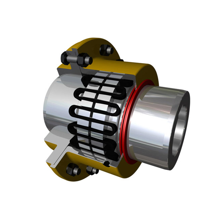
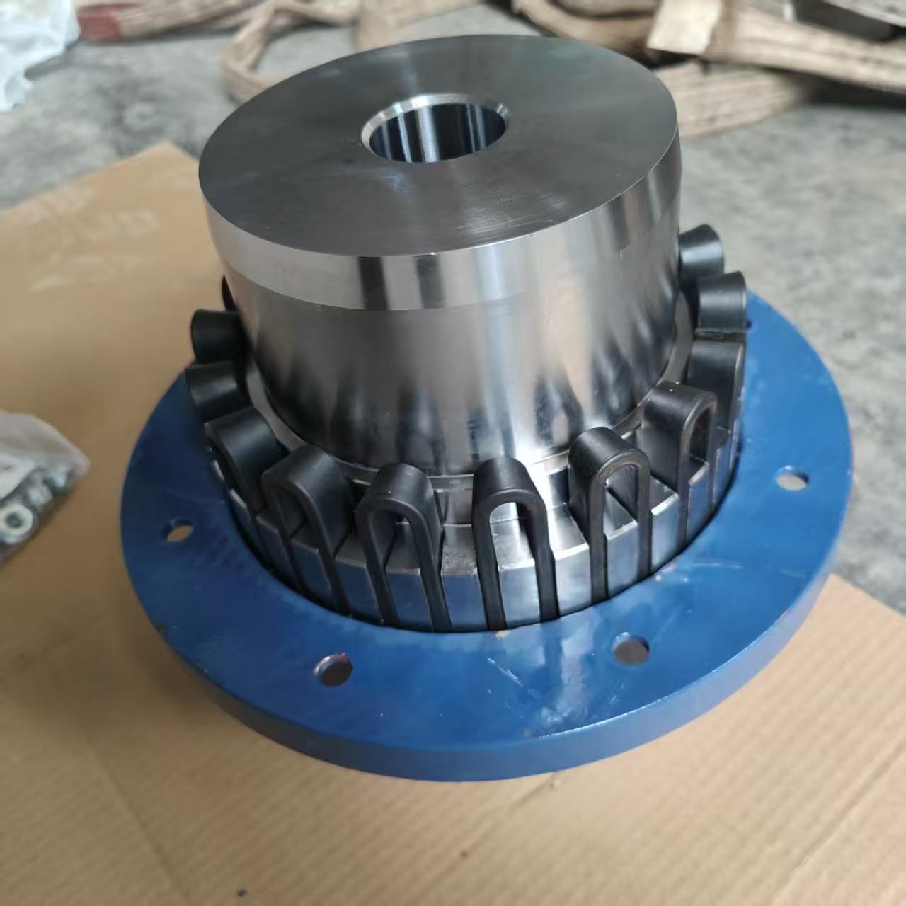
The flexible element in a grid coupling is a deflecting steel spring, not a universal joint. It accommodates misalignment by flexing, but that flex comes with a mechanical cost: the grid element experiences alternating stress at each shaft revolution, and the stress amplitude grows with the misalignment magnitude. At rated misalignment, the grid's stress cycle is within its endurance limit for the design life. At two times rated misalignment, the stress cycle doubles in amplitude, and the fatigue life of the grid element falls to a fraction of the design value — meaning a coupling running chronically at double its rated misalignment fails in months instead of years.
The seal is the second casualty of poor alignment. A grid coupling running with significant angular misalignment generates a prying action on the seal lip at each revolution, forcing lubricant past the seal and introducing contamination. The seal failure rate in poorly aligned couplings is consistently higher than in properly aligned ones, and a leaking coupling that admits water or dust accelerates grid wear further, creating a compounding failure sequence that ends with a grid replacement far sooner than expected.
Alignment Targets for Grid Couplings: The 50% Rule
The catalog rating for a grid coupling's angular and parallel misalignment is a maximum — the value at which the coupling can still operate without damage, not the value it should be set to. The industry consensus target for installation alignment is approximately 50% of the rated value, leaving the remaining capacity to accommodate thermal growth, pipe strain, and the settling that occurs in the first weeks of operation on a new machine.
A grid coupling rated for 0.5 degrees of angular misalignment should be aligned to within 0.25 degrees at ambient, cold conditions. One rated for 0.4 millimeters of parallel offset should be set within 0.2 millimeters. These are not arbitrarily tight numbers — they are achievable with standard alignment tools and reflect the practical margin that keeps the coupling within its design life window after the machine warms up and the pipe strain develops.
Thermal Growth Compensation in Grid Coupling Alignment
Shafts grow when they heat up. A motor shaft running at 60 degrees Celsius is measurably longer than the same shaft at 20 degrees — the growth is a function of the shaft material, the temperature differential, and the shaft length between the coupling hub and the bearing. If the coupling is aligned cold with both shafts at ambient temperature, the motor shaft's thermal growth during warm-up pushes the coupling hub axially, changing the angular and parallel relationship between the two shafts.
The standard approach to grid coupling alignment in thermal applications is to set the cold alignment with a deliberate offset that anticipates the thermal growth. For a motor on adjustable feet, the shim stack is adjusted so that when the motor reaches operating temperature, the feet have expanded by the calculated amount and the shafts are aligned. The calculation uses the thermal expansion coefficient of steel — approximately 12 micrometers per meter per degree Celsius — applied to the shaft center distance and the temperature rise.
For large machines with significant temperature differentials, a laser alignment system with thermal growth compensation is the practical tool. The laser system measures the cold alignment, the operator enters the bearing housing temperatures and shaft dimensions, and the software calculates the target cold offset. For small to medium grid coupling installations with moderate thermal differential, the rim-and-face method with a standard thermal growth table is adequate.
Alignment Methods and Their Accuracy
Three alignment methods span the accuracy range from rough to precision. The straightedge-and-feeler method — a straightedge across the coupling faces, feeler gauges at the rim — provides approximately ±0.5 millimeter accuracy. It is useful for checking gross misalignment on large machines where the coupling is inaccessible, but it is not adequate for setting a grid coupling to the 50% target on precision service.
The reverse-dial indicator method — one dial indicator on each hub, reading at 12, 3, 6, and 9 o'clock positions — provides ±0.05 millimeter accuracy and is the standard for most industrial alignment work. The procedure requires careful setup: both indicators zeroed, readings taken at consistent positions, and the mathematics of converting dial readings to shaft positions applied correctly. A common error is failing to account for the coupling hub's diameter when converting rim readings to angular values, producing an angular alignment that appears correct but is actually off by a factor of two.
Laser alignment systems are the current standard for grid coupling alignment in plants that prioritize uptime. Modern systems with detector arrays and software that models thermal growth, soft foot, and document the results to a maintenance management system provide accuracy of ±0.01 millimeter with full traceability. The cost of the equipment is justified in plants with more than twenty critical machines, and the accuracy improvement over dial indicator methods consistently reduces bearing wear and vibration across the aligned fleet.
Soft Foot and Its Effect on Grid Coupling Alignment
Soft foot — a machine foot that does not sit flat on its foundation, leaving a gap under the bolt — distorts the machine's frame when the foot bolts are tightened. The distortion changes the shaft positions, and a grid coupling that was aligned before tightening the bolts may be significantly misaligned afterward. The sequence that eliminates soft foot effects: loosen all machine feet, set the machine in position, place shims under the high foot until the machine sits stable without bolt pressure, then tighten the anchor bolts evenly in a diagonal pattern, checking alignment after each tightening step.
Laser alignment systems measure soft foot directly, reporting the gap under each foot as a dial reading. Correcting soft foot before taking the final alignment reading removes one of the largest sources of alignment error in industrial installations. A grid coupling aligned with uncorrected soft foot carries the distortion into the machine's bearing loads from the first start, and the vibration and bearing wear that result are incorrectly attributed to the coupling rather than the alignment procedure that set it.
Maintenance Alignment Checks on Grid Couplings
Initial alignment does not persist indefinitely. Thermal cycling, vibration, pipe strain, and foundation settlement all shift shaft positions over months and years. A grid coupling that was at 0.15 millimeters of parallel offset at commissioning may be at 0.35 millimeters after two years of thermal cycling — still within the coupling's rating, but past the 50% target and accumulating wear faster than the design assumes.
Establishing a scheduled alignment check interval — annually for standard-service machines, six months for heavy-shock or high-temperature duty — catches the drift before it reaches levels that accelerate grid wear. The check is quick with a laser system: attach the targets, take the measurement, compare to the baseline. A drift of more than 0.1 millimeters in either angular or parallel misalignment on a critical machine is grounds for corrective action before the next scheduled run.
Frequently Asked Questions
What alignment target should a grid coupling meet at installation?
The standard target is 50% of the coupling's rated misalignment value — approximately 0.25 degrees angular and 0.2 millimeters parallel offset for a coupling rated at 0.5 degrees and 0.4 millimeters respectively. This margin accommodates thermal growth and pipe strain during operation without pushing the coupling beyond its rated capacity.
Does a grid coupling still need alignment if it is flexible?
Yes. The flexibility is within a limited window, and running outside that window — chronic misalignment at double the rated value — reduces grid fatigue life dramatically. Proper alignment sets the coupling within the window from the start; poor alignment converts the "flexible" element into a wear accelerator for the grid, the seals, and the connected bearings.
How do I account for thermal growth in coupling alignment?
Calculate the shaft's thermal growth using the steel expansion coefficient of approximately 12 micrometers per meter per degree Celsius of temperature rise, applied to the shaft center distance. Set the cold alignment with a deliberate offset — the motor shims adjusted so that when the shaft heats to operating temperature, the expansion brings the shafts into alignment. Laser systems calculate this automatically from bearing temperature inputs.
What is the correct alignment check interval for grid couplings?
Annual checks are standard for moderate-duty machines. Six-month intervals are appropriate for heavy-shock, high-temperature, or high-vibration applications where thermal cycling is more aggressive. Any significant vibration increase on a machine with a grid coupling warrants an alignment check before assuming the coupling itself has failed.
Conclusion
Grid coupling alignment requirements are not suggestions — they are the engineering basis for the coupling's design life. Angular and parallel misalignment within 50% of the rated value, with thermal growth compensation applied for machines with significant temperature differential, sets the coupling up for the service life the catalog promises. Soft foot corrected, alignment checked at commissioning and on a maintenance schedule, and any vibration increase investigated with an alignment check before the coupling is blamed — these are the habits that keep a grid coupling operating as a reliable, replaceable, shock-absorbing element rather than a recurring maintenance expense that shortens the life of the bearings it was supposed to protect.
References
AGMA 9002-B04 — Flexible Couplings: Design Considerations and Selection
ISO 14691:2008 — Flexible Couplings: Design, Selection and Application
Pai, N. (2015). Practical Machinery Management for Process Plants, 4th Edition. Gulf Professional Publishing.
Bloch, H.P. & Geitner, F.K. (2011). Machinery Failure Analysis and Troubleshooting, 4th Edition. Butterworth-Heinemann.
API 686 — Recommended Practice for Machinery Installation and Installation Design