

Among the many types of flexible couplings used in industrial power transmission, the drum gear coupling occupies a distinctive position thanks to its ability to transmit high torque while accommodating substantial shaft misalignment. For engineers, procurement specialists, and maintenance professionals encountering this coupling type for the first time, understanding its operating principles and performance characteristics is essential for making informed specification decisions.
This introductory guide explains how a drum gear coupling works, what advantages it offers compared to other coupling designs, and where it is most commonly applied across industrial sectors. The goal is to provide a clear, practical foundation for anyone involved in coupling selection, installation, or maintenance.
What Is a Drum Gear Coupling?
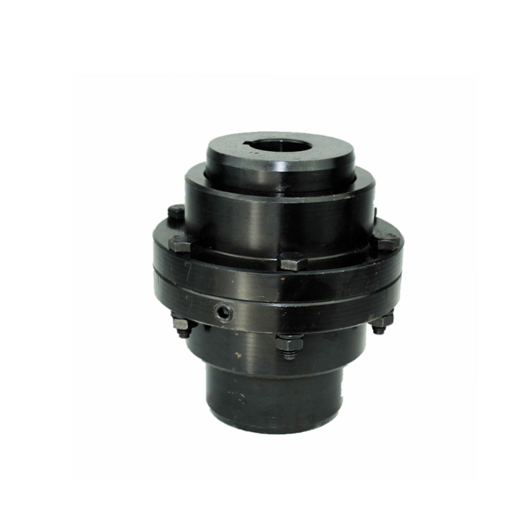
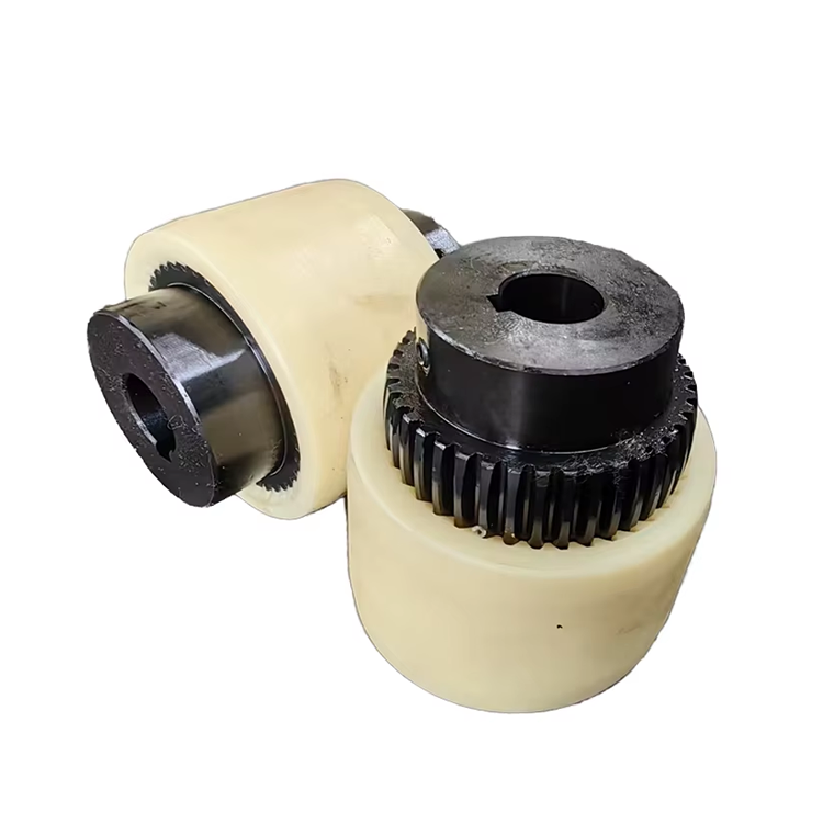
A drum gear coupling is a mechanical power transmission device that uses internal and external gear teeth to connect two shafts while allowing for angular, parallel, and axial misalignment. The coupling consists of two hubs with external gear teeth that engage with a sleeve — sometimes called a bushing or spacer — featuring matching internal gear teeth. The tooth profile follows an involute curve, enabling smooth torque transfer even under misaligned conditions.
The term "drum" refers to the barrel-shaped crown modification applied to the gear teeth. Unlike straight spur gear teeth, drum-shaped teeth have a curved profile along their length that allows the teeth to maintain contact across a wider surface area even when the coupling hubs are angularly misaligned. This crown modification is the key design feature that gives the drum gear coupling its distinctive misalignment capability.
Drum gear couplings belong to the broader category of gear couplings, which also includes straight-tooth and crowned-tooth designs. Among these variants, the drum (crowned) gear tooth profile offers the best balance of torque capacity, misalignment accommodation, and service life for most industrial applications.
How Does the Drum Gear Coupling Transmit Torque?
Torque transmission occurs through the meshing engagement of the external hub teeth with the internal sleeve teeth. As the driving shaft rotates, it drives the hub, whose external teeth push against the internal teeth of the sleeve, which in turn drives the second hub and the driven shaft. The distributed tooth contact across multiple teeth simultaneously ensures that no single tooth carries excessive load under normal operating conditions.
When angular misalignment exists between the connected shafts, the drum-shaped teeth pivot slightly within the internal tooth spaces, maintaining contact while accommodating the angular difference. This rocking motion occurs thousands of times per revolution at high speeds, which is why proper lubrication of the tooth mesh is essential for long service life.
The continuous sliding contact between external and internal teeth generates friction heat that must be dissipated through the lubricant and coupling housing. At very high speeds or under heavy misalignment, the heat generation rate increases significantly, requiring enhanced lubrication or cooling provisions to maintain acceptable operating temperatures.
Advantages of Drum Gear Coupling Designs
The drum gear coupling offers several compelling advantages that explain its widespread use in heavy industrial applications. First, its compact dimensions relative to torque capacity make it suitable for installations with limited space. A drum gear coupling of a given bore size typically transmits 30-50% more torque than an elastomeric coupling of the same envelope dimensions.
Second, the design accommodates all three types of misalignment simultaneously — angular, parallel, and axial — within published ratings. This versatility simplifies installation where multiple misalignment sources exist, such as thermal growth, foundation settlement, and pipe strain acting together on the machine train.
Third, drum gear couplings maintain consistent performance across a wide temperature range. Unlike elastomeric couplings whose flexible elements soften at high temperatures and stiffen at low temperatures, gear couplings rely on metal-to-metal contact that performs reliably from -40°F to over 400°F with appropriate lubricant selection. This temperature stability is particularly valuable in outdoor installations and process plants with wide ambient variations.
Key Design Parameters to Understand
Several design parameters define a specific drum gear coupling's capabilities and limitations. The number of teeth on the hub and sleeve determines the contact area and load distribution. Higher tooth counts provide more contact area but reduce individual tooth size, while lower counts offer larger teeth with greater bending strength per tooth.
The pressure angle — typically 20 degrees for standard industrial drum gear couplings — affects the force components transmitted through the tooth mesh. Standard 20-degree pressure angles provide a well-balanced combination of torque capacity and thrust loading. Some specialized designs use modified pressure angles for specific application requirements.
Hub and sleeve material specifications directly determine torque capacity and service life. Common materials include hardened alloy steel hubs (typically 42CrMo4 or equivalent) and normalized or case-hardened sleeve internals. Surface hardness and treatment processes such as carburizing or nitriding significantly influence tooth wear resistance and coupling durability.
Common Industrial Applications
Drum gear coupling technology finds extensive use across multiple industrial sectors. In steel processing, drum gear couplings connect motor to gearbox inputs on rolling mill drives, where high torque and occasional shock loads demand robust coupling performance. The coupling's ability to accommodate misalignment from thermal expansion of hot mill housings is particularly valuable in these installations.
Petrochemical and refinery applications employ drum gear couplings on pump drives, compressor trains, and mixer agitators. The compact dimensions fit within tight installation envelopes common in process plant equipment layouts. High-temperature process environments are well-suited to the all-metal construction and temperature-stable performance characteristics.
Mining operations use drum gear couplings on conveyor drives, crusher applications, and mill drives where dust, moisture, and vibration create challenging operating environments. Sealed and grease-lubricated designs protect internal tooth surfaces from contamination while providing reliable torque transmission under heavy loads.
Marine propulsion systems utilize drum gear couplings to connect main engines to reduction gearboxes. The coupling's ability to accommodate hull deflection and thermal differential between engine and gearbox makes it well-suited for the dynamic conditions encountered at sea.
Lubrication and Maintenance Basics
Proper lubrication is the single most important maintenance factor affecting drum gear coupling service life. The sliding contact between meshing teeth requires a lubricant film that separates metal surfaces, reducing friction and preventing adhesive wear. Most industrial drum gear couplings use semi-fluid grease lubricants with extreme pressure additives.
Lubricant selection should match the operating speed and temperature range. High-speed applications require lower-viscosity grease to minimize churning losses and heat generation, while slow-speed, heavy-load applications benefit from higher-viscosity formulations. Always use the coupling manufacturer's recommended lubricant specifications to ensure compatibility with seal materials and tooth surface treatments.
Recommended lubrication intervals typically range from 3 to 12 months depending on operating conditions. More frequent lubrication is warranted in contaminated environments, high-temperature applications, or installations operating near rated misalignment limits. During lubrication, inspect the discharged grease for metal particles — an indication of tooth wear requiring investigation.
Frequently Asked Questions
What is the difference between a drum gear coupling and a standard gear coupling?
The primary distinction is the tooth profile. Drum gear couplings feature barrel-shaped (crowned) teeth that curve along their length, providing improved contact distribution under angular misalignment. Standard straight-tooth gear couplings have parallel-sided teeth that concentrate contact at tooth edges under misalignment, resulting in higher localized stress and accelerated wear. The drum profile significantly extends service life in misaligned installations.
Can a drum gear coupling handle shock loads?
Drum gear couplings transmit shock loads directly through the rigid metal-to-metal tooth mesh. Unlike elastomeric couplings that absorb shock energy through flexible element deformation, gear couplings offer limited inherent shock damping. For applications with significant shock loading, consider combining the drum gear coupling with a torque-limiting device or selecting a coupling with a higher service factor to provide additional overload margin.
How much misalignment can a drum gear coupling accommodate?
Typical rated values range from 0.25 to 1.0 degrees of angular misalignment per flex plane and 0.010 to 0.060 inches of parallel offset, depending on coupling size and model. These are maximum rated values — continuous operation should target no more than 50-60% of these limits to achieve rated service life. Exceeding rated misalignment dramatically reduces tooth contact quality and accelerates wear.
What type of grease is best for drum gear couplings?
Use a high-quality coupling grease with EP (extreme pressure) additives, good mechanical stability, and appropriate viscosity for the operating speed and temperature range. NLGI Grade 0 or 1 semi-fluid grease is common for most industrial applications. Always consult the coupling manufacturer's lubrication specifications, as incompatible greases can cause seal degradation or inadequate film formation at the tooth mesh.
How do I know when a drum gear coupling needs replacement?
Key indicators include increased vibration at coupling harmonic frequencies, abnormal heat generation, grease contamination with metallic particles during lubrication, and visible tooth wear or pitting during inspection. Many facilities schedule drum gear coupling overhauls at published manufacturer intervals — typically 3 to 5 years for continuous duty applications — based on operating conditions and load severity classification.
Conclusion
The drum gear coupling provides a proven, high-performance solution for industrial power transmission applications requiring high torque capacity, compact dimensions, and reliable misalignment accommodation. Its all-metal construction delivers consistent performance across wide temperature ranges, while the crowned tooth design ensures even load distribution under real-world misalignment conditions. For engineers and procurement professionals new to gear coupling technology, understanding these fundamental principles — combined with proper lubrication practices — enables confident specification and maintenance decisions that deliver long-term equipment reliability.
References
AGMA 9002-B04 — Flexible Couplings: Design Considerations and Selection
ISO 14691:2008 — Flexible Couplings: Design, Selection and Application
Api 671 — Special Purpose Couplings for Petroleum, Chemical, and Gas Industry Services
Dudley, D.W. (1994). Handbook of Practical Gear Design. CRC Press.
ISO 1328-1:2014 — Flank Profile Tolerance for Cylindrical Gears