

Every coupling comes with an installation manual. Most manuals describe the steps in the correct order — inspect, mount, align, lubricate, torque — but they assume a clean bench, a calibrated heater, fresh shims, and a technician who has done this before. The actual field condition is different: a shaft that has been running hot, hubs that have been on the same shaft for years and resist removal, shims that are bent, and a production supervisor who needs the machine running in the next two hours. This article covers the installation sequence as it actually happens in a plant, with the decisions that the manual does not make explicit.
Pre-Installation Inspection: The Step Most People Skip
Before the new coupling goes on the shaft, both shafts and both hub bores are inspected. This is not optional. A shaft with corrosion, brinelling, or fretting damage at the bearing journal will not hold the hub correctly even if the bore fit is perfect, and a hub bore that has ovality from previous over-heating will not seat concentrically on the shaft regardless of the fit class. A 0.02 millimeter out-of-round in the bore becomes 0.04 millimeter runout once the hub is on the shaft, and that runout becomes vibration that shows up at motor speed within the first few hours of operation.
The inspection takes fifteen minutes with a micrometer on the shaft journals, a bore gauge in the hub bores, and a visual check of the shaft keyways. If any measurement is outside the coupling catalog's specified limits, correct the shaft before mounting the hub. Installing a new coupling on a worn shaft does not fix the shaft — it hides the problem until the coupling shows the symptoms.
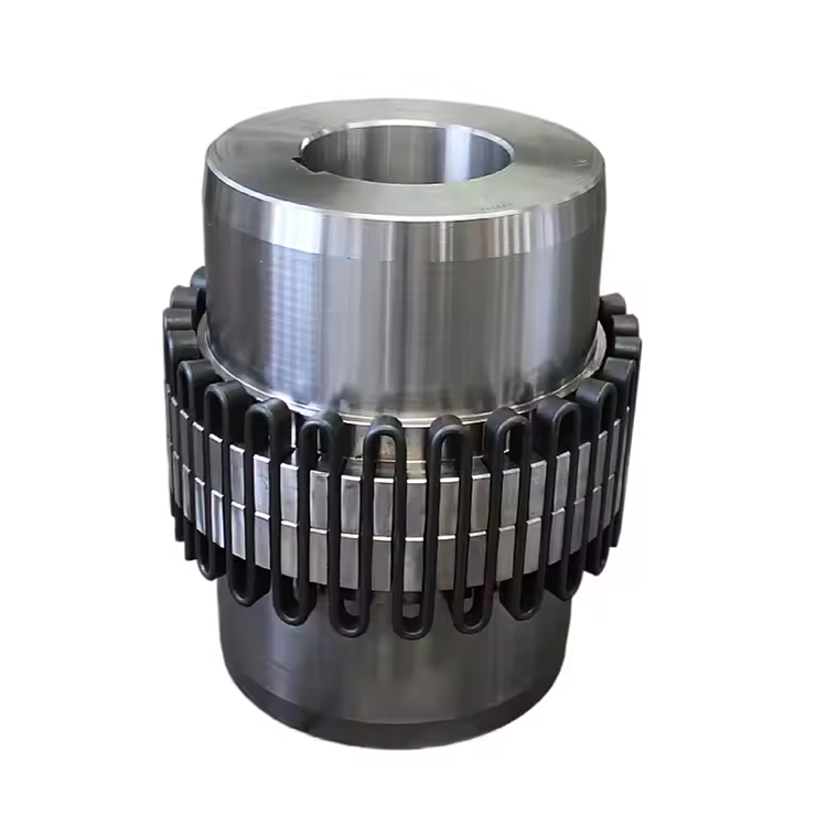
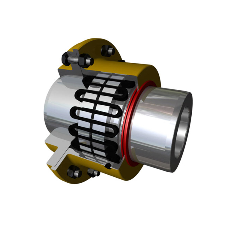
Hub Mounting: Fit Class Determines the Method
The fit class specified for the coupling hub determines how the hub goes onto the shaft. An interference or press fit requires controlled heating — oil bath, induction heater, or torch — to expand the hub bore enough to slide onto the shaft without requiring force that damages the bore, the shaft, or the technician. A transition fit or clearance fit can often be assembled cold with light tapping, provided the shaft and bore are clean, dry, and free of burrs.
Installation errors cluster around two failure modes: heating a hub to the wrong temperature, or assembling a press fit cold. Heating above approximately 200 degrees Celsius for a standard steel hub risks altering the microstructure of the bore surface, which changes the bore dimensions and the fit quality. For a typical induction heater, 120 to 150 degrees Celsius is the standard target — enough to reduce the interference enough for assembly, not enough to affect the material properties. Cold pressing an interference-fit hub risks cracking the hub at the keyway root, which is the most common catastrophic failure mode for improperly assembled gear and grid coupling hubs.
The Key and Keyway: Torque Path Before Alignment
The key is the primary torque-transmitting element in a clearance-fit or transition-fit coupling hub, and its fit in the keyway is as important as the fit of the hub on the shaft. A key that rocks in the hub keyway transfers torque unevenly, hammering the slot edges with every revolution and generating the fretting debris that shows up in the next oil sample or the next coupling drain. A key that is too tight to seat fully leaves a gap between the key and the shaft key, and the hub runs on the key instead of the shaft — guaranteed to fail early.
The correct procedure: check the key fit in the shaft keyway first, then check the fit in the hub keyway, then verify the assembled height — the key should seat flush in the shaft keyway without forcing. When the shaft keyway and hub keyway are both to standard tolerance, the key goes in with light hand pressure. If it requires a hammer, something is wrong with the dimensions or the tolerance class.
Alignment: From Rim-and-Face to Laser Systems
Alignment is where the installation earns its quality or spends the rest of its operating life paying for its shortcuts. The two practical field methods are the rim-and-face dial indicator method and the laser alignment system. Rim-and-face is the traditional approach: one dial indicator on the outside diameter of one hub reading rim movement, a second indicator reading face gap at the coupling perimeter, with readings taken at 12, 3, 6, and 9 o'clock positions. The mathematics converts dial readings to shaft center positions, accounting for the dial indicator's radius.
Laser alignment systems have become the standard in plants that run a structured maintenance program. The laser emitter and detector attach to each hub face, the system measures the relative positions continuously, and the software calculates the shim corrections needed for both angular and parallel misalignment simultaneously. The accuracy advantage is real — laser systems achieve ±0.01 millimeter precision compared to ±0.05 to ±0.1 millimeter for a skilled dial indicator user — but the larger practical advantage is the software's soft-foot correction, its ability to model thermal growth from bearing temperature inputs, and its automatic documentation to the maintenance management system.
Soft Foot: The Alignment Destroyer Nobody Checks
Soft foot is a gap between a machine foot and its mounting surface, present when the bolt is loosened and the machine settles onto its shims. When the anchor bolt is tightened, the machine frame distorts to close the gap, and that distortion changes the shaft positions — usually pushing one shaft away from or toward the other. A coupling aligned with uncorrected soft foot will be misaligned after the bolts are tightened, and the misalignment will be misdiagnosed as coupling failure when the vibration shows up in the first vibration route.
The soft foot sequence: loosen all machine anchor bolts, place dial indicators on each corner of the machine, and read the gap under each bolt individually with the bolt loose. Any reading above approximately 0.05 millimeters at any corner should be corrected with shim stock before proceeding to alignment. Laser systems measure soft foot automatically as part of the alignment routine, which is one of their most valuable features for alignment quality.
Lubrication and Seal Integrity at Start-Up
The lubrication procedure depends on the coupling type. A grid coupling filled with EP grease requires a specific fill volume — usually stated as filling to the level plug — with excess grease causing churning, heat, and seal leakage at speed. The fill level for a gear coupling is different from a grid coupling, and the grease type may also differ. Using the wrong grease — standard lithium soap in a coupling that requires polyurea thickener, or non-EP grease in a high-load grid coupling — accelerates seal wear and reduces the lubrication film thickness at the tooth contacts.
Seal integrity is checked before start-up by verifying that both seals are in their grooves, seated flush with the housing face, and free of cuts or distortion from the installation process. A damaged seal on a coupling that will run at 1,750 RPM or above will leak within the first hour of operation, contaminating the surrounding area and admitting the dust or moisture that ends the coupling's service life early.
Final Checks Before Start-Up
The pre-start checklist is brief but mandatory: verify hub set screws or clamp bolts are tight to the specified torque, verify the coupling is at the correct axial position with the specified gap or preload, verify the guards are installed and secure, verify no tools or rags are left in the coupling area, and verify the motor rotation direction before coupling the shafts. The rotation check alone prevents the mechanical damage that occurs when a coupling is first connected to a motor running in the wrong direction — uncommon but destructive when it happens.
Initial start-up run at no load for thirty to sixty minutes allows the coupling to reach operating temperature and confirms that no abnormal noise or vibration appears. The temperature of the coupling housing at operating conditions should be stable and within the catalog-specified maximum — typically 80 to 100 degrees Celsius above ambient for standard operation. A coupling that continues to heat after the first hour is either over-filled with grease, misaligned beyond the rated capacity, or running above its speed or torque rating.
Frequently Asked Questions
What temperature should I heat a coupling hub to for installation?
For standard steel coupling hubs with an interference fit, 120 to 150 degrees Celsius is the typical target for induction or oil bath heating. This is enough to expand the bore for assembly without altering the material microstructure or damaging seal components. Always verify against the coupling manufacturer's specific instructions — some heat-treated hubs have lower maximum recommended temperatures.
How do I know if the keyway fit is correct?
The key should seat in the shaft keyway with light hand pressure only. If it requires a hammer, the keyway width is out of tolerance. After installing the hub, verify the key does not protrude above the hub bore face and that there is no gap between the key and the shaft keyway root — a gap indicates the key is rocking and will generate fretting debris under torque.
What is the most common alignment mistake in the field?
Aligning the coupling before correcting soft foot. A machine with a significant soft foot condition will shift when the anchor bolts are tightened, and the alignment measurement taken before bolt tightening will not reflect the machine's actual condition under load. Always check and correct soft foot before the first alignment measurement.
How much grease should a grid coupling hold?
The correct fill volume is stated on the coupling or in the manufacturer's documentation, typically filling to the level plug. Under-filling reduces lubrication at the grid-slot contacts; over-filling causes churning, heat buildup, and seal leakage at speed. Always verify the specified fill volume for the specific coupling size and model, as the volume changes with the coupling size.
Conclusion
Coupling installation is a sequence of decisions, not just steps. The pre-inspection catches shaft and bore problems before they become coupling failures. The hub mounting method follows from the fit class, not convenience. The keyway check prevents the fretting damage that ruins a new coupling in months. Alignment is only reliable after soft foot is corrected. Lubrication follows the specification, not the grease can that is open. And the pre-start checklist prevents the mechanical damage that turns a routine installation into a repair job. A plant that follows this sequence on every coupling installation gets the design life the coupling was built for — and the maintenance team stops spending time on failures that installation would have prevented.
References
AGMA 9002-B04 — Flexible Couplings: Design Considerations and Selection
ISO 14691:2008 — Flexible Couplings: Design, Selection and Application
Pai, N. (2015). Practical Machinery Management for Process Plants, 4th Edition. Gulf Professional Publishing.
Bloch, H.P. & Geitner, F.K. (2011). Machinery Failure Analysis and Troubleshooting, 4th Edition. Butterworth-Heinemann.
API 686 — Recommended Practice for Machinery Installation and Installation Design