

The world of industrial power transmission is full of half-truths and inherited assumptions. A maintenance engineer who has always used the same coupling type on a pump shaft will continue ordering it without question — until the bearing fails prematurely or the coupling destroys itself at 18 months instead of the expected six years. These failures are rarely the fault of the coupling itself; they are the consequence of misunderstandings that accumulate over decades of industry habit.
Coupling is a mechanical component that connects two rotating shafts to transmit torque while accommodating misalignment. It sounds simple. In practice, the gap between this simple definition and correct application is where significant cost and downtime live. This article identifies and dispels eight misunderstandings that are most damaging to industrial operations.
1. Misalignment Tolerance Is a One-Number Specification
The most widespread misunderstanding is treating misalignment tolerance as a single figure. In reality, a coupling must simultaneously accommodate three types of misalignment: angular, parallel (radial), and axial. Each type is independent, and exceeding any one of them will cause failure regardless of how well the others are managed.
Most flexible coupling types — including grid couplings, jaw couplings, and disc couplings — publish separate figures for each misalignment type. A coupling specified with "3° angular tolerance" may have only 0.3 mm of parallel offset capacity at the operating speed. Procurement teams who evaluate couplings solely on published misalignment figures without reading the fine print frequently select components that fail in the field despite seemingly adequate specifications.
Field measurement data from industrial surveys indicates that over 60% of coupling failures in conveyor drive systems are directly traceable to misalignment conditions exceeding manufacturer specifications — not to material defects or torque overload.
2. Any Flexible Coupling Can Absorb Shock Loads
Flexibility and shock load capacity are not the same thing. A coupling with high flexibility (large angular or parallel deflection range) often has lower torque capacity because its flexible elements are designed to deflect rather than transmit high loads. Conversely, a coupling designed for high torque transmission may have very limited angular deflection.
Applications with frequent start-stop cycles, motor-driven conveyors, or equipment with high inertial mass require a coupling specifically rated for shock load or dynamic torque conditions. Not all flexible couplings are designed to handle repeated peak torques exceeding 200% of rated torque — yet many are sold and installed in exactly these conditions because buyers assume "flexible" means "shock-proof."
3. Torque Rating Alone Determines Coupling Size
Selecting a coupling by matching torque rating to motor output is necessary but insufficient. The complete selection process requires three additional calculations: peak torque (which may be 2–5× average running torque during acceleration), the bore capacity (shaft diameter range the coupling can accommodate), and the critical speed rating of the assembly.
A coupling selected purely on torque may have adequate strength but insufficient bore capacity for the shaft — requiring costly machined sleeves or adaptor bushes that add complexity and potential failure points. Alternatively, the coupling's balance rating may conflict with the high-speed requirements of the driven equipment. Professional coupling distributors provide selection worksheets that account for all four parameters simultaneously.
4. All Grid Couplings Are Functionally Identical
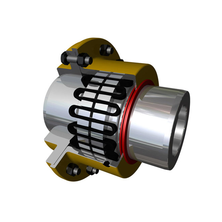
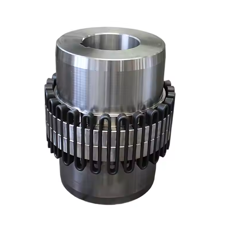
This assumption is particularly costly in heavy industrial applications. The Industrial Grid Coupling category encompasses a wide range of design philosophies, material specifications, and quality tiers. A grid coupling with a high-tensile steel hub and a precision-ground, hardened grid element performs fundamentally differently from an economy version with cast hubs and unhardened grids — even if the torque ratings appear comparable on paper.
The key differentiating factors include grid material hardness (typically Rockwell C 42–52 for durability), hub surface finish, bolt preload specifications, and the quality of the coating on steel members. In applications like Long Distance Conveyors where coupling replacement requires significant downtime, paying a 15–20% premium for a superior grid coupling often yields a 3–5× improvement in service life.
5. Once Installed, Couplings Require No Ongoing Attention
Predictive maintenance programs routinely monitor bearings, motors, and gearboxes — and then ignore the coupling entirely until it fails. This is a significant oversight. Visual inspection of the coupling element (grid, jaw, disc, or gear) can identify wear patterns that predict imminent failure 4–8 weeks in advance, allowing planned replacement during a scheduled outage rather than an emergency shutdown.
For Industrial Grid Coupling installations, the inspection protocol is straightforward: check for grid fatigue cracks, measure hub-to-hub distance to detect axial wear, inspect for corrosion of grid slots, and verify bolt torque. An experienced maintenance technician can complete this inspection in under 30 minutes per coupling. The cost of this inspection is negligible compared to the revenue loss from an unplanned conveyor shutdown in a mining or port operation.
6. Rebuilt or Refurbished Couplings Match Original Performance
When a coupling fails in an expensive location — a long distance overland conveyor, for example — the temptation to rebuild it rather than replace it is understandable. However, rebuilt couplings frequently fail at accelerated rates because the rebuild process cannot reproduce the original material specifications, heat treatment, or dimensional tolerances.
The grid element of an Industrial Grid Coupling is the most critical rebuilt component. Original equipment manufacturers (OEMs) heat-treat the grid steel to specific hardness levels through controlled quenching and tempering. After-market grids may be made from generic spring steel that has different fatigue properties, different hardness progression with temperature cycling, and different dimensional consistency. The cost saving from using a rebuilt grid is typically 30–50% of a new OEM grid — but the risk premium often exceeds this saving through increased failure probability.
7. Alignment Does Not Matter if the Coupling Is Flexible
Perhaps the most dangerous misunderstanding in the industry. Flexible coupling elements do accommodate misalignment — but they wear faster when misalignment is present. The relationship is not linear: doubling the angular misalignment does not double wear rate; it may quadruple it or worse, depending on speed and load.
Industry best practice requires laser alignment to within ±0.05 mm for precision equipment and ±0.13 mm for general industrial shaft connections. Even when a flexible coupling is installed, the goal should be to achieve the best practical alignment, treating the coupling's flexibility as a safety margin rather than a design allowance. This distinction is critical for continuous process industries where a Coupling failure on a critical service pump can halt an entire production line.
8. The Cheapest Initial Cost Equals the Lowest Total Cost
Life cycle cost analysis consistently demonstrates that the coupling component represents less than 2% of the total installed cost of most industrial drive systems — yet it is frequently sourced on price alone without evaluating service history, lead time, or technical support capability.
A procurement manager who selects a T20 Grid Coupling supplier based solely on unit price may achieve a 10% saving on the coupling purchase — while accepting a 40% higher probability of coupling failure, a 3-week lead time versus a 2-day lead time for stocked items, and no engineering support for installation or failure analysis. The total cost of one unplanned downtime event on a 500 tph conveyor typically far exceeds the entire annual coupling budget for that facility.
Conclusion
These eight misunderstandings share a common root: treating coupling as a commodity rather than a precision-engineered component whose selection has measurable consequences for equipment reliability, maintenance cost, and production continuity. The industrial operations that achieve the lowest total cost of ownership for their rotating equipment are those that invest engineering time in correct coupling specification, maintenance time in regular inspection, and procurement time in qualifying suppliers on technical capability rather than unit price alone.
The decision framework for coupling selection should be methodical: calculate torque and dynamic load requirements accurately, measure the actual shaft sizes and critical speed constraints, evaluate misalignment conditions using precision instruments, and then — only then — evaluate suppliers on price within the range of technically qualified candidates. This sequence, while it takes more time upfront, consistently delivers superior results in industrial power transmission applications.
Frequently Asked Questions (FAQ)
Q1: How do I know if my application exceeds the misalignment capacity of a given coupling?
The most reliable method is direct field measurement using a dial indicator or laser alignment tool. Measure angular alignment at the coupling faces and parallel offset at mid-coupling. Compare these figures to the manufacturer's published tolerances for each misalignment type. If any measured value exceeds 50% of the published tolerance, a more tolerant coupling type or improved alignment procedure is recommended. In most Long Distance Conveyors, alignment tolerances of ±0.10 mm angular and ±0.15 mm parallel are achievable with laser alignment tools and should be specified as the installation standard.
Q2: What is the difference between a gear coupling and an Industrial Grid Coupling?
Gear couplings and grid couplings are both classified as flexible couplings but operate on fundamentally different principles. A gear coupling transmits torque through the meshing of gear teeth — it requires lubrication and has limited misalignment capacity. An Industrial Grid Coupling transmits torque through a spring-like grid element that slides in and out of slotted flanged hubs — it requires minimal lubrication (periodic greasing), handles both angular and parallel misalignment, and is particularly well-suited to high-torque, high-speed applications such as Long Distance Conveyors and large pump drives.
Q3: How often should grid couplings be inspected?
In heavy industrial environments — mining, steel, cement, port handling — quarterly visual inspections are recommended for Industrial Grid Coupling installations. Annual inspections should include torque verification of all fasteners, dimensional measurement of hub-to-hub spacing, and visual inspection of the grid element for fatigue cracks or permanent deformation. For non-critical applications, annual inspection intervals are generally sufficient.
Q4: Can a T20 Grid Coupling be used in high-temperature environments?
T20 Grid Coupling specifications vary by manufacturer, but standard grid couplings are rated for continuous operating temperatures up to approximately 120°C. For higher temperatures, special high-temperature grids made from alloy steels or with specialized heat treatment are required. Always verify the temperature rating with the T20 Grid Coupling Supplier and ensure the coupling is listed in the equipment's formal datasheet rather than relying on general marketing specifications.
Q5: What is the expected service life of an Industrial Grid Coupling in a continuous conveyor application?
Under ideal conditions — correct alignment within specifications, appropriate lubrication, torque within rated capacity, and ambient temperatures within design range — an Industrial Grid Coupling in a continuous conveyor application typically achieves 25,000 to 50,000 operating hours before grid element replacement is advisable. In harsh environments with contamination, vibration, or frequent misalignment, this may reduce to 8,000–15,000 hours. Regular inspection and prompt element replacement at signs of fatigue are the primary drivers of extended service life.
References:
Mobley, R. K. (2014). Maintenance Engineering Handbook (8th ed.). McGraw-Hill Education.
Neumann, C. (2018). Industrial Couplings: Selection, Installation and Maintenance. Engineering Failure Analysis, 89, 218–235.
Shigley, J. E., & Mischke, C. R. (2020). Mechanical Engineering Design (11th ed.). McGraw-Hill.
American Society of Mechanical Engineers. (2019). ASME B106.1M-1995: Design of Transmission Shafting. ASME.
Pimbley, J. M., & Glaeser, W. A. (2017). Mechanical Power Transmission. Industrial Press.